
User's Manual
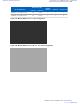


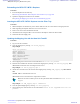


Table Of Contents
- 5827 Exhibit D - User Information
- Tune-Up Procedure
- User Manual
- MANUAL COVER PAGE
- Copyrights
- CMM Labeling and Disclosure Table
- Service Information
- Document History
- Contents
- List of Figures
- List of Tables
- List of Processes
- List of Procedures
- About MTS LiTE, MTS 2 and MTS 4 Installation, Configuration and Basic Service Manual
- MTS Overview
- General Safety
- Radio Frequency Distribution System
- RFDS Theory of Operation
- MTS LiTE and MTS 2 RFDS
- MTS 4 RFDS
- Expansion Cabinet RFDS
- Site Controller
- XHUB Controller
- Base Radio
- Power Supply Unit
- Cooling Fans
- Technical Specifications
- Environmental and Standards Specifications
- Cabinet and Module Specifications
- MTS Cabinets Frequency Range
- Dimensions of the MTS Cabinets
- RF Specifications
- Transmitter Specifications
- Receiver Specifications
- Site Controller Specifications
- Internal GPS Module Input Specifications
- MTS LiTE / MTS 2 Duplexer Specifications
- MTS LiTE / MTS 2 Preselector Specifications
- MTS 4 Duplexer Specifications
- MTS 4 Post Filter Specifications
- MTS 4 Preselector Specifications
- Auto Tune Cavity Combiner (ATCC) Specifications
- Manual Tune Cavity Combiner (MTCC) Specifications
- Hybrid Combiner Specifications
- Base Radio Specifications
- Power Supply Unit Specifications
- XHUB Controller Specifications
- RX Splitter Specifications
- MTS LiTE, MTS 2, and MTS 4 Connectors
- Expansion Options
- MTS 4 Outdoor Enclosure
- Appendix A: Field Replaceable Units (FRUs)
- Appendix B: Planned Maintenance Inspection (PMI)
- Appendix C: Static Precautions and ESD Strap
- Appendix D: TETRA/Dimetra Acronyms

Hybrid Combiner
The Hybrid Combiner is a part of the transmitter path in the RF Distribution System. The Hybrid Combiner provides
very reliable combining of up to two transmitters. The Hybrid Combiner has no limitations in respect to channel
spacing of the TX channels; however, for frequency planning and interference reasons, at least 50 kHz is
recommended.
Figure 145: Hybrid Combiner
The TX signals from two Base Radios are attached to the respective Hybrid Combiner inputs. The combined signal at
the Hybrid Combiner out port is then applied to the Duplexer.
The Hybrid Combiner contains one printed circuit board.
Replacing the Hybrid Combiner
Process:
1 Remove the Hybrid Combiner.
See Removing the Hybrid Combiner on page 241.
2 Reinstall the Hybrid Combiner.
See
Reinstalling the Hybrid Combiner on page 242.
Removing the Hybrid Combiner
Procedure:
1
Warning: RF energy hazard and potential equipment damage.
Switch OFF the Power Supply Unit to prevent accidental contact with high energy and injury to personnel.
Radio Frequency Distribution System | 241
6802800U74-AD | September 2014 | Send Feedback
Applicant: Motorola Solutions
Equipment Type: ABZ89FC5827 / 109AB-5827
Exhibit D2