
User's Manual
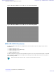


Table Of Contents
- 5827 Exhibit D - User Information
- Tune-Up Procedure
- User Manual
- MANUAL COVER PAGE
- Copyrights
- CMM Labeling and Disclosure Table
- Service Information
- Document History
- Contents
- List of Figures
- List of Tables
- List of Processes
- List of Procedures
- About MTS LiTE, MTS 2 and MTS 4 Installation, Configuration and Basic Service Manual
- MTS Overview
- General Safety
- Radio Frequency Distribution System
- RFDS Theory of Operation
- MTS LiTE and MTS 2 RFDS
- MTS 4 RFDS
- Expansion Cabinet RFDS
- Site Controller
- XHUB Controller
- Base Radio
- Power Supply Unit
- Cooling Fans
- Technical Specifications
- Environmental and Standards Specifications
- Cabinet and Module Specifications
- MTS Cabinets Frequency Range
- Dimensions of the MTS Cabinets
- RF Specifications
- Transmitter Specifications
- Receiver Specifications
- Site Controller Specifications
- Internal GPS Module Input Specifications
- MTS LiTE / MTS 2 Duplexer Specifications
- MTS LiTE / MTS 2 Preselector Specifications
- MTS 4 Duplexer Specifications
- MTS 4 Post Filter Specifications
- MTS 4 Preselector Specifications
- Auto Tune Cavity Combiner (ATCC) Specifications
- Manual Tune Cavity Combiner (MTCC) Specifications
- Hybrid Combiner Specifications
- Base Radio Specifications
- Power Supply Unit Specifications
- XHUB Controller Specifications
- RX Splitter Specifications
- MTS LiTE, MTS 2, and MTS 4 Connectors
- Expansion Options
- MTS 4 Outdoor Enclosure
- Appendix A: Field Replaceable Units (FRUs)
- Appendix B: Planned Maintenance Inspection (PMI)
- Appendix C: Static Precautions and ESD Strap
- Appendix D: TETRA/Dimetra Acronyms

Reinstalling the MTS LiTE / MTS 2 Duplexer
Procedure:
1 Insert the Duplexer into the filter tray.
See Inserting the MTS LiTE / MTS 2 Duplexer into the Filter Tray on page 240.
2 Update the mapping list with the new unit TrackID.
See
Updating the Mapping List with the New Unit TrackID on page 240.
Inserting the MTS LiTE / MTS 2 Duplexer into the Filter Tray
Procedure:
1 Slide the Duplexer into the filter tray in the cabinet. Make sure the rear center tab fits in the appropriate slot.
2 While supporting the Duplexer fasten the two screws at the front.
3 Fasten screw in the center tab behind the antenna.
4 Attach all RX, TX and signal cables to be connected to the Duplexer. Fasten the antenna cable.
5 Switch ON the Power Supply Unit.
Updating the Mapping List with the New Unit TrackID
Procedure:
1 Log on to the Site Controller.
2 View the mapping list by entering: can check_mapping.
Step example:
Units are present:
Device Track ID
DPM 1 JTH0500101
PSU 1 JTH0500200
Units are not present:
DPM 2 JTH0500105
Track ID not mapped:
JTH0500102
3 On the mapping list, locate the removed unit indicated as Units are not present.
4 Delete the old CAN Bus unit from the CAN Bus unit mapping list by entering: can remove_mapping <X>.
<X> identifies the old unit name and is digit between 0 and 3.
Step example: can remove_mapping dpm 2.
5 Add the new CAN Bus unit to the CAN Bus unit mapping list by entering: add_mapping dpm<X><track
ID>.
<track ID> is a Track ID of the new unit.
<X> identifies the new unit name and is a digit between 0 and 3.
Note: The new unit Track ID is present on the replaced unit label and indicated as Track ID not
mapped.
Step example: can add_mapping dpm 2 JTH0500102
6 View the updated mapping list by entering: can check_mapping.
7 On the mapping list, check that there are no units labeled as Track ID not mapped or Units are not
present.
240 | Radio Frequency Distribution System
Send Feedback | September 2014 | 6802800U74-AD
Applicant: Motorola Solutions
Equipment Type: ABZ89FC5827 / 109AB-5827
Exhibit D2