
User's Manual
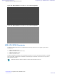


Table Of Contents
- 5827 Exhibit D - User Information
- Tune-Up Procedure
- User Manual
- MANUAL COVER PAGE
- Copyrights
- CMM Labeling and Disclosure Table
- Service Information
- Document History
- Contents
- List of Figures
- List of Tables
- List of Processes
- List of Procedures
- About MTS LiTE, MTS 2 and MTS 4 Installation, Configuration and Basic Service Manual
- MTS Overview
- General Safety
- Radio Frequency Distribution System
- RFDS Theory of Operation
- MTS LiTE and MTS 2 RFDS
- MTS 4 RFDS
- Expansion Cabinet RFDS
- Site Controller
- XHUB Controller
- Base Radio
- Power Supply Unit
- Cooling Fans
- Technical Specifications
- Environmental and Standards Specifications
- Cabinet and Module Specifications
- MTS Cabinets Frequency Range
- Dimensions of the MTS Cabinets
- RF Specifications
- Transmitter Specifications
- Receiver Specifications
- Site Controller Specifications
- Internal GPS Module Input Specifications
- MTS LiTE / MTS 2 Duplexer Specifications
- MTS LiTE / MTS 2 Preselector Specifications
- MTS 4 Duplexer Specifications
- MTS 4 Post Filter Specifications
- MTS 4 Preselector Specifications
- Auto Tune Cavity Combiner (ATCC) Specifications
- Manual Tune Cavity Combiner (MTCC) Specifications
- Hybrid Combiner Specifications
- Base Radio Specifications
- Power Supply Unit Specifications
- XHUB Controller Specifications
- RX Splitter Specifications
- MTS LiTE, MTS 2, and MTS 4 Connectors
- Expansion Options
- MTS 4 Outdoor Enclosure
- Appendix A: Field Replaceable Units (FRUs)
- Appendix B: Planned Maintenance Inspection (PMI)
- Appendix C: Static Precautions and ESD Strap
- Appendix D: TETRA/Dimetra Acronyms

Figure 143: MTS 2 Duplexer
Note: Unused RX outputs should be terminated.
The duplex spacing between a transmit frequency and the corresponding receive frequency is 10 MHz, with the
transmit frequency highest. This leaves a 5 MHz spacing between the lowest possible transmit frequency and the
highest possible receive frequency.
For MTS 2 260 MHz, the duplex spacing between a transmit frequency and the corresponding receive frequency is 9
MHz, and leaves a 3 MHz spacing between the lowest possible transmit frequency and the highest possible receive
frequency.
For 800 MHz, the duplex spacing between a transmit frequency and the corresponding receive frequency is 45 MHz,
and leaves a 19 MHz spacing between the lowest possible transmit frequency and the highest possible receive
frequency in each duplexer.
For 900 MHz, the duplex spacing between a transmit frequency and the corresponding receive frequency is 15 MHz,
and leaves a 10 MHz spacing between the lowest possible transmit frequency and the highest possible receive
frequency.
The MTS LiTE/MTS 2 Duplexer has 2 RX outputs and can handle a maximum power of 60 watts.
Note: Unused RX outputs should be terminated.
The receiver LNA and splitter provides multiple receive signal ports. An amplified output is provided for connection
to the other cabinet in an expansion configuration.
The digital power monitor (DPM) is a directional coupler that measures forward and reverse Power. Power and
VSWR information can be read through the CAN bus.
238 | Radio Frequency Distribution System
Send Feedback | September 2014 | 6802800U74-AD
Applicant: Motorola Solutions
Equipment Type: ABZ89FC5827 / 109AB-5827
Exhibit D2