
User's Manual
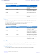
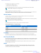
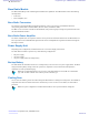


Table Of Contents
- 5827 Exhibit D - User Information
- Tune-Up Procedure
- User Manual
- MANUAL COVER PAGE
- Copyrights
- CMM Labeling and Disclosure Table
- Service Information
- Document History
- Contents
- List of Figures
- List of Tables
- List of Processes
- List of Procedures
- About MTS LiTE, MTS 2 and MTS 4 Installation, Configuration and Basic Service Manual
- MTS Overview
- General Safety
- Radio Frequency Distribution System
- RFDS Theory of Operation
- MTS LiTE and MTS 2 RFDS
- MTS 4 RFDS
- Expansion Cabinet RFDS
- Site Controller
- XHUB Controller
- Base Radio
- Power Supply Unit
- Cooling Fans
- Technical Specifications
- Environmental and Standards Specifications
- Cabinet and Module Specifications
- MTS Cabinets Frequency Range
- Dimensions of the MTS Cabinets
- RF Specifications
- Transmitter Specifications
- Receiver Specifications
- Site Controller Specifications
- Internal GPS Module Input Specifications
- MTS LiTE / MTS 2 Duplexer Specifications
- MTS LiTE / MTS 2 Preselector Specifications
- MTS 4 Duplexer Specifications
- MTS 4 Post Filter Specifications
- MTS 4 Preselector Specifications
- Auto Tune Cavity Combiner (ATCC) Specifications
- Manual Tune Cavity Combiner (MTCC) Specifications
- Hybrid Combiner Specifications
- Base Radio Specifications
- Power Supply Unit Specifications
- XHUB Controller Specifications
- RX Splitter Specifications
- MTS LiTE, MTS 2, and MTS 4 Connectors
- Expansion Options
- MTS 4 Outdoor Enclosure
- Appendix A: Field Replaceable Units (FRUs)
- Appendix B: Planned Maintenance Inspection (PMI)
- Appendix C: Static Precautions and ESD Strap
- Appendix D: TETRA/Dimetra Acronyms

Note:
MTS LiTE supports one Duplexer.
Because the MTS 2 has only up to two carriers, there is no need for Post Filters for non-duplexed
operation (you can achieve non-duplexed operation by using the Duplexer as the Post Filter and not
using the receive path of the Duplexer).
• Hybrid Combiner. MTS 2 can have either a Hybrid Combiner for transmission on one antenna, or without
combining for transmission on two separate antennas.
MTS 2 is equipped with a digital voltage standing wave ratio (VSWR) monitor to ensure site availability at remote
low-traffic sites and for public safety customers. The digital VSWR monitor can make a quite accurate VSWR
reading because the measurement is relative between the forward and reverse power.
The VSWR monitor does not have the same accuracy in power reading as the digital power monitor (DPM) in the
MTS 4, but it still allows a cost-effective monitoring of the integrity of the antenna.
MTS LiTE and MTS 2 Filter Tray
The MTS LiTE filter tray can carry one Duplexer and one Preselector or one Duplexer and no Preselector. The
antenna connectors from the Duplexer extend from the MTS LiTE junction panel while antenna connection from the
Preselector is connected via the use of cable. Antenna cables are connected directly onto the filters.
Note:
In Table 71: MTS LiTE RF Configurations on page 231, Low Power is valid for 400 MHz, while High
Power is valid for 400 MHz, 800MHz and 900 MHz. The numbers illustrated are applicable for TETRA.
The MTS 2 filter tray can carry up to two Duplexers and one Preselector or one Duplexer and two Preselectors. There
is also room for a Hybrid Combiner. The antenna connectors extend from the MTS 2 junction panel and antenna
cables are connected directly onto the filters.
Note: In Table 72: MTS 2 RF Configurations on page 232,
Low Power is valid for 400 MHz and 260
MHz, while High Power is valid for 400 MHz, 800MHz and 900 MHz. The numbers illustrated are
applicable for TETRA with TEDS numbers within parentheses.
Table 71: MTS LiTE RF Configurations on page 231 lists all filters configurations for MTS LiTE and Figure 135:
MTS LiTE TX/RX on 1 ant. - Filter Configuration on page 232 and Figure 136: MTS LiTE TX/RX on 1 ant., RX on 1
ant - Filter Configuration on page 232 show the positions of filters in the filter tray.
Table 71: MTS LiTE RF Configurations
RF Configuration
Max Power [W]
Duplexer Preselector
Low Pwr High Pwr
TX/RX on 1 ant. 25 40 1 -
TX/RX on 1 ant., RX on 1 ant. 25 40
1 1
Radio Frequency Distribution System | 231
6802800U74-AD | September 2014 | Send Feedback
Applicant: Motorola Solutions
Equipment Type: ABZ89FC5827 / 109AB-5827
Exhibit D2