
User's Manual
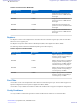
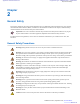


Table Of Contents
- 5827 Exhibit D - User Information
- Tune-Up Procedure
- User Manual
- MANUAL COVER PAGE
- Copyrights
- CMM Labeling and Disclosure Table
- Service Information
- Document History
- Contents
- List of Figures
- List of Tables
- List of Processes
- List of Procedures
- About MTS LiTE, MTS 2 and MTS 4 Installation, Configuration and Basic Service Manual
- MTS Overview
- General Safety
- Radio Frequency Distribution System
- RFDS Theory of Operation
- MTS LiTE and MTS 2 RFDS
- MTS 4 RFDS
- Expansion Cabinet RFDS
- Site Controller
- XHUB Controller
- Base Radio
- Power Supply Unit
- Cooling Fans
- Technical Specifications
- Environmental and Standards Specifications
- Cabinet and Module Specifications
- MTS Cabinets Frequency Range
- Dimensions of the MTS Cabinets
- RF Specifications
- Transmitter Specifications
- Receiver Specifications
- Site Controller Specifications
- Internal GPS Module Input Specifications
- MTS LiTE / MTS 2 Duplexer Specifications
- MTS LiTE / MTS 2 Preselector Specifications
- MTS 4 Duplexer Specifications
- MTS 4 Post Filter Specifications
- MTS 4 Preselector Specifications
- Auto Tune Cavity Combiner (ATCC) Specifications
- Manual Tune Cavity Combiner (MTCC) Specifications
- Hybrid Combiner Specifications
- Base Radio Specifications
- Power Supply Unit Specifications
- XHUB Controller Specifications
- RX Splitter Specifications
- MTS LiTE, MTS 2, and MTS 4 Connectors
- Expansion Options
- MTS 4 Outdoor Enclosure
- Appendix A: Field Replaceable Units (FRUs)
- Appendix B: Planned Maintenance Inspection (PMI)
- Appendix C: Static Precautions and ESD Strap
- Appendix D: TETRA/Dimetra Acronyms

Base Radio Module
The Base Radio (BR) provides reliable digital communication capabilities. Each Base Radio contains the following
subcomponents:
• Transceiver
• Power Amplifier (PA)
Base Radio Transceiver
The transceiver provides the BRs with signal transmission, receiving, processing, and modulation functions,
incorporating a Base Radio Controller (BRC), Receiver (RCV), and Exciter (EXC).
The BRC serves as the main controller of the Base Radio, and provides signal processing and operational control for
the other Base Radio modules.
Base Radio Power Amplifier
The Power Amplifier (PA) in conjunction with the exciter provides the transmitter functions for the Base Radio. The
PA accepts the low-level modulated RF signal from the exciter and amplifies the signal for transmission through the
RF output connector.
Power Supply Unit
Depending on the configuration, the MTS includes one or two Power Supply Units (PSUs).
The PSU allows the MTS to operate in any of the following configurations:
•
DC power supply
• AC power supply
• AC power supply with a DC backup battery
Backup Battery
The PSU handles the automatic switchover to a backup battery in the event of an AC power supply failure. The MTS
charges the backup battery during normal AC operation. A temperature sensor monitors the backup batteries
temperature to ensure optimum charging.
Note: The recommended batteries to be used are a Valve Regulated Lead Acid (VRLA) recombination
type, with -48 VDC nominal. Such as Enersys Power safe VFT type.
Cooling Fans
One or more fan modules generate an airflow through the MTS cabinets to manage their temperature. Each module is
comprised of two fans. Revolution of the fans is monitored by a sensor. In the event of a failure, an alarm will be
generated.
Note: Low-power configurations of MTS LiTE and MTS 2 can be operated without cooling fans.
50 | MTS Overview
Send Feedback | September 2014 | 6802800U74-AD
Applicant: Motorola Solutions
Equipment Type: ABZ89FC5827 / 109AB-5827
Exhibit D2