
User's Manual
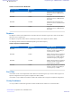


Table Of Contents
- 5827 Exhibit D - User Information
- Tune-Up Procedure
- User Manual
- MANUAL COVER PAGE
- Copyrights
- CMM Labeling and Disclosure Table
- Service Information
- Document History
- Contents
- List of Figures
- List of Tables
- List of Processes
- List of Procedures
- About MTS LiTE, MTS 2 and MTS 4 Installation, Configuration and Basic Service Manual
- MTS Overview
- General Safety
- Radio Frequency Distribution System
- RFDS Theory of Operation
- MTS LiTE and MTS 2 RFDS
- MTS 4 RFDS
- Expansion Cabinet RFDS
- Site Controller
- XHUB Controller
- Base Radio
- Power Supply Unit
- Cooling Fans
- Technical Specifications
- Environmental and Standards Specifications
- Cabinet and Module Specifications
- MTS Cabinets Frequency Range
- Dimensions of the MTS Cabinets
- RF Specifications
- Transmitter Specifications
- Receiver Specifications
- Site Controller Specifications
- Internal GPS Module Input Specifications
- MTS LiTE / MTS 2 Duplexer Specifications
- MTS LiTE / MTS 2 Preselector Specifications
- MTS 4 Duplexer Specifications
- MTS 4 Post Filter Specifications
- MTS 4 Preselector Specifications
- Auto Tune Cavity Combiner (ATCC) Specifications
- Manual Tune Cavity Combiner (MTCC) Specifications
- Hybrid Combiner Specifications
- Base Radio Specifications
- Power Supply Unit Specifications
- XHUB Controller Specifications
- RX Splitter Specifications
- MTS LiTE, MTS 2, and MTS 4 Connectors
- Expansion Options
- MTS 4 Outdoor Enclosure
- Appendix A: Field Replaceable Units (FRUs)
- Appendix B: Planned Maintenance Inspection (PMI)
- Appendix C: Static Precautions and ESD Strap
- Appendix D: TETRA/Dimetra Acronyms

The following Cavity Combiner (CC) are available:
• Auto Tune Cavity Combiners (ATCC)
• Manual Tune Cavity Combiners (MTCC)
MTCCs are functionally the same as ATCCs except that they are tuned manually instead of electronically.
Note: 260 MHz configurations do not support MTCC.
MTS LiTE and MTS 2 do not support Cavity Combiners.
Minimum channel spacing of the TX channels is 150 kHz while the recommended channel spacing is 250 kHz. This
limitation applies to all Cavity Combiners in all cabinets connected to the same transmit antenna.
Hybrid Combiner
A Hybrid Combiner combines RF signal from a number of different base radios into one transmitter filter.
The Hybrid Combiner (HC) combines up to two transmitters.
The combiner has no limitations in respect to channel spacing of the TX channels. However, for frequency planning
and interference reasons, at least 50 kHz is recommended.
Note: MTS LiTE does not support Hybrid Combiners.
The following table shows the frequency range covered by various Hybrid Combiners.
Table 4: Hybrid Combiner — Frequency Range
Hybrid Combiner Frequency Range
260 MHz 260 MHz — 275 MHz
400 MHz
350 MHz — 470 MHz
800 MHZ 850 MHz — 870 MHz
900 MHz 932 MHz — 942 MHz
Rx Splitter
The RX splitter is a passive device, receiving the signal from the Expansion Out connector of the Duplexer/
Preselector in the MTS 4 Prime Cabinet and then distributes it to the Base Radios in the MTS 4 Expansion Cabinet.
Site Controller Module
The Site Controller (SC) controls resources within the base station, including frequency and slot assignment to mobile
stations. The Site Controller incorporates a Global Positioning System (GPS), which receives signals for developing
high-precision system timing signals.
The Site Controller communicates with the Base Radio through the 100Base-T Ethernet interface and with the
network through an X.21 or E1 link.
XHUB
The eXpansion HUB (XHUB) is a non-intelligent switching and interface module, which plugs into the Site
Controller slot of an MTS 4 Expansion Cabinet. It is connected through the Expansion Cab output of the Site
Controller to the Prime Cab connector of the XHUB.
MTS Overview | 49
6802800U74-AD | September 2014
|
Send Feedback
Applicant: Motorola Solutions
Equipment Type: ABZ89FC5827 / 109AB-5827
Exhibit D2