
User's Manual
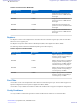
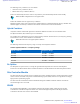


Table Of Contents
- 5827 Exhibit D - User Information
- Tune-Up Procedure
- User Manual
- MANUAL COVER PAGE
- Copyrights
- CMM Labeling and Disclosure Table
- Service Information
- Document History
- Contents
- List of Figures
- List of Tables
- List of Processes
- List of Procedures
- About MTS LiTE, MTS 2 and MTS 4 Installation, Configuration and Basic Service Manual
- MTS Overview
- General Safety
- Radio Frequency Distribution System
- RFDS Theory of Operation
- MTS LiTE and MTS 2 RFDS
- MTS 4 RFDS
- Expansion Cabinet RFDS
- Site Controller
- XHUB Controller
- Base Radio
- Power Supply Unit
- Cooling Fans
- Technical Specifications
- Environmental and Standards Specifications
- Cabinet and Module Specifications
- MTS Cabinets Frequency Range
- Dimensions of the MTS Cabinets
- RF Specifications
- Transmitter Specifications
- Receiver Specifications
- Site Controller Specifications
- Internal GPS Module Input Specifications
- MTS LiTE / MTS 2 Duplexer Specifications
- MTS LiTE / MTS 2 Preselector Specifications
- MTS 4 Duplexer Specifications
- MTS 4 Post Filter Specifications
- MTS 4 Preselector Specifications
- Auto Tune Cavity Combiner (ATCC) Specifications
- Manual Tune Cavity Combiner (MTCC) Specifications
- Hybrid Combiner Specifications
- Base Radio Specifications
- Power Supply Unit Specifications
- XHUB Controller Specifications
- RX Splitter Specifications
- MTS LiTE, MTS 2, and MTS 4 Connectors
- Expansion Options
- MTS 4 Outdoor Enclosure
- Appendix A: Field Replaceable Units (FRUs)
- Appendix B: Planned Maintenance Inspection (PMI)
- Appendix C: Static Precautions and ESD Strap
- Appendix D: TETRA/Dimetra Acronyms

Table 2: Preselector Filter Bandwidth
MTS Frequency Bandwidth Description
260 MHz 6 MHz Designed to block transmitter fre-
quencies as close as 6 MHz from its
band edges.
400 MHz 5 MHz Designed to block transmitter fre-
quencies as close as 5 MHz from its
band edges.
800 MHz
19 MHz Designed to block transmitter fre-
quencies as close as 19 MHz from its
band edges.
900 MHz 5 MHz Designed to block transmitter fre-
quencies as close as 5 MHz from its
band edges.
Duplexer
The Duplexer consists of two bandpass filters. One filter allows the transmitter signal to pass, while the other filter
allows the receiver signal to pass.
The Duplexer incorporates both an Receiver Multicoupler (RMC) and a Digital Power Meter (DPM).
The following table describes filter bandwidth depending on the MTS frequency.
Table 3: Duplexer Filter Bandwidth
MTS Frequency Bandwidth Duplex Spacing
260 MHz 6 MHz Duplex spacing between a transmitter
frequency and the corresponding re-
ceive frequency is 9 MHz.
400 MHz
5 MHz Duplex spacing between a transmitter
frequency and the corresponding re-
ceive frequency is 10 MHz, with the
transmitter frequency being higher.
800 MHz 19 MHz Duplex spacing between a transmitter
frequency and the corresponding re-
ceive frequency is 45 MHz.
900 MHz 5 MHz Duplex spacing between a transmitter
frequency and the corresponding re-
ceive frequency is 15 MHz.
Post Filter
A Post Filter consist of one bandpass filter which allows the transmitter signal to pass. The Post Filter supports non-
duplexed configurations and incorporates a Digital Power Meter (DPM).
A Post Filter is only available for the MTS 4 as MTS LiTE and MTS 2 do not support non-duplexed configurations.
Cavity Combiners
A Cavity Combiner combines RF signal from a number of different base radios into one transmitter filter.
48 | MTS Overview
Send Feedback | September 2014 | 6802800U74-AD
Applicant: Motorola Solutions
Equipment Type: ABZ89FC5827 / 109AB-5827
Exhibit D2