
User's Manual


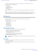
Table Of Contents
- 5827 Exhibit D - User Information
- Tune-Up Procedure
- User Manual
- MANUAL COVER PAGE
- Copyrights
- CMM Labeling and Disclosure Table
- Service Information
- Document History
- Contents
- List of Figures
- List of Tables
- List of Processes
- List of Procedures
- About MTS LiTE, MTS 2 and MTS 4 Installation, Configuration and Basic Service Manual
- MTS Overview
- General Safety
- Radio Frequency Distribution System
- RFDS Theory of Operation
- MTS LiTE and MTS 2 RFDS
- MTS 4 RFDS
- Expansion Cabinet RFDS
- Site Controller
- XHUB Controller
- Base Radio
- Power Supply Unit
- Cooling Fans
- Technical Specifications
- Environmental and Standards Specifications
- Cabinet and Module Specifications
- MTS Cabinets Frequency Range
- Dimensions of the MTS Cabinets
- RF Specifications
- Transmitter Specifications
- Receiver Specifications
- Site Controller Specifications
- Internal GPS Module Input Specifications
- MTS LiTE / MTS 2 Duplexer Specifications
- MTS LiTE / MTS 2 Preselector Specifications
- MTS 4 Duplexer Specifications
- MTS 4 Post Filter Specifications
- MTS 4 Preselector Specifications
- Auto Tune Cavity Combiner (ATCC) Specifications
- Manual Tune Cavity Combiner (MTCC) Specifications
- Hybrid Combiner Specifications
- Base Radio Specifications
- Power Supply Unit Specifications
- XHUB Controller Specifications
- RX Splitter Specifications
- MTS LiTE, MTS 2, and MTS 4 Connectors
- Expansion Options
- MTS 4 Outdoor Enclosure
- Appendix A: Field Replaceable Units (FRUs)
- Appendix B: Planned Maintenance Inspection (PMI)
- Appendix C: Static Precautions and ESD Strap
- Appendix D: TETRA/Dimetra Acronyms

Figure 2: MTS 2 Cabinet
The modules that comprise the MTS 2 cabinet vary based on the type of configuration chosen. A typical configuration
includes the following modules:
• Duplexer
• Preselector
•
Hybrid Combiner
• Site Controller
• Base Radio(s)
• Power Supply Unit
The door of the cabinet has a lock to prevent unauthorized opening. Unauthorized opening of the door generates an
alarm.
For a complete description of each module, refer to the appropriate chapter. Each chapter provides the theory of
operation, a description of switches, indicators and connectors, and FRU replacement procedures for each module.
Configuration and testing, and troubleshooting for MTSs are provided in separate chapters.
44 | MTS Overview
Send Feedback | September 2014 | 6802800U74-AD
Applicant: Motorola Solutions
Equipment Type: ABZ89FC5827 / 109AB-5827
Exhibit D2