
User's Manual


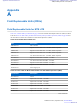
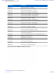
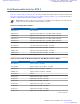
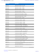
Table Of Contents
- 5827 Exhibit D - User Information
- Tune-Up Procedure
- User Manual
- MANUAL COVER PAGE
- Copyrights
- CMM Labeling and Disclosure Table
- Service Information
- Document History
- Contents
- List of Figures
- List of Tables
- List of Processes
- List of Procedures
- About MTS LiTE, MTS 2 and MTS 4 Installation, Configuration and Basic Service Manual
- MTS Overview
- General Safety
- Radio Frequency Distribution System
- RFDS Theory of Operation
- MTS LiTE and MTS 2 RFDS
- MTS 4 RFDS
- Expansion Cabinet RFDS
- Site Controller
- XHUB Controller
- Base Radio
- Power Supply Unit
- Cooling Fans
- Technical Specifications
- Environmental and Standards Specifications
- Cabinet and Module Specifications
- MTS Cabinets Frequency Range
- Dimensions of the MTS Cabinets
- RF Specifications
- Transmitter Specifications
- Receiver Specifications
- Site Controller Specifications
- Internal GPS Module Input Specifications
- MTS LiTE / MTS 2 Duplexer Specifications
- MTS LiTE / MTS 2 Preselector Specifications
- MTS 4 Duplexer Specifications
- MTS 4 Post Filter Specifications
- MTS 4 Preselector Specifications
- Auto Tune Cavity Combiner (ATCC) Specifications
- Manual Tune Cavity Combiner (MTCC) Specifications
- Hybrid Combiner Specifications
- Base Radio Specifications
- Power Supply Unit Specifications
- XHUB Controller Specifications
- RX Splitter Specifications
- MTS LiTE, MTS 2, and MTS 4 Connectors
- Expansion Options
- MTS 4 Outdoor Enclosure
- Appendix A: Field Replaceable Units (FRUs)
- Appendix B: Planned Maintenance Inspection (PMI)
- Appendix C: Static Precautions and ESD Strap
- Appendix D: TETRA/Dimetra Acronyms

Configuration
No configuration in itself is needed for the module cage, but the Power Supply Unit needs to be configured and this is
described in Updating the Mapping List with the New PSU TrackID on page 303
.
Installation and configuration of additional Base Radios are described separately in Additional Base Radio for
Existing Module Cage in MTS 4 on page 381.
Furthermore, if an additional Site Controller is ordered as a separate expansion kit, it needs to be installed and
configured, see Redundant Site Controller on page 389.
Redundant XHUB Controller
It is possible to add an redundant XHUB Controller to an MTS 4 Expansion Cabinet.
Note: In order to be able to expand to a redundant XHUB Controller, a redundant Site Controller must be
present in the MTS 4 Prime Cabinet.
The additional XHUB Controller is delivered with the expansion kit that includes required equipment and cables.
Adding a Redundant XHUB Controller
Procedure:
1 Wear an ESD strap and connect its cable to a verified good ground. This strap must be worn to prevent ESD
damage to any components.
2 Remove XHUB Controller blind plate if such exist in the upper module cage of the MTS 4 Expansion Cabinet.
3 Label the cables with labels included in the expansion kit.
4 Connect the Ethernet cables to the Base Radio(s) according to the scheme below:
Part no Cable type From To
3066544B02 Ethernet cable BR4 / SC2 XHUB2 / BR4
3066544B15 Ethernet cable BR1 / SC2 XHUB2 / BR1
3066544B16 Ethernet cable BR2 / SC2 XHUB2 / BR2
3066544B01 Ethernet cable BR3 / SC2 XHUB2 / BR3
Note:
Ethernet cables stated above derives from the Base Radio(s) in the MTS 4 Expansion Cabinet.
At this stage only connect the cables to the Base Radio(s).
5 Strap the cables.
6 Install the additional XHUB Controller. Use handle to slide the unit into the chassis.
Important: Connect the ribbon cables at the rear before sliding the unit in to the chassis.
7 Secure the XHUB Controller in the chassis with two M4X10 captive screws.
8 Connect the Ethernet cables to the unit as tagged earlier.
9 Connect the 3066544B12 cable that derives from the upper Site Controller in the MTS 4 Prime Cabinet (Exp Cab
connector).
10 Reconnect the power cables to the MTS Power Supply Units.
Expansion Options | 401
6802800U74-AD | September 2014 | Send Feedback
Applicant: Motorola Solutions
Equipment Type: ABZ89FC5827 / 109AB-5827
Exhibit D2