
User's Manual
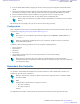
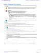
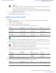

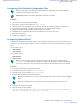


Table Of Contents
- 5827 Exhibit D - User Information
- Tune-Up Procedure
- User Manual
- MANUAL COVER PAGE
- Copyrights
- CMM Labeling and Disclosure Table
- Service Information
- Document History
- Contents
- List of Figures
- List of Tables
- List of Processes
- List of Procedures
- About MTS LiTE, MTS 2 and MTS 4 Installation, Configuration and Basic Service Manual
- MTS Overview
- General Safety
- Radio Frequency Distribution System
- RFDS Theory of Operation
- MTS LiTE and MTS 2 RFDS
- MTS 4 RFDS
- Expansion Cabinet RFDS
- Site Controller
- XHUB Controller
- Base Radio
- Power Supply Unit
- Cooling Fans
- Technical Specifications
- Environmental and Standards Specifications
- Cabinet and Module Specifications
- MTS Cabinets Frequency Range
- Dimensions of the MTS Cabinets
- RF Specifications
- Transmitter Specifications
- Receiver Specifications
- Site Controller Specifications
- Internal GPS Module Input Specifications
- MTS LiTE / MTS 2 Duplexer Specifications
- MTS LiTE / MTS 2 Preselector Specifications
- MTS 4 Duplexer Specifications
- MTS 4 Post Filter Specifications
- MTS 4 Preselector Specifications
- Auto Tune Cavity Combiner (ATCC) Specifications
- Manual Tune Cavity Combiner (MTCC) Specifications
- Hybrid Combiner Specifications
- Base Radio Specifications
- Power Supply Unit Specifications
- XHUB Controller Specifications
- RX Splitter Specifications
- MTS LiTE, MTS 2, and MTS 4 Connectors
- Expansion Options
- MTS 4 Outdoor Enclosure
- Appendix A: Field Replaceable Units (FRUs)
- Appendix B: Planned Maintenance Inspection (PMI)
- Appendix C: Static Precautions and ESD Strap
- Appendix D: TETRA/Dimetra Acronyms

Hybrid Combiner Expansion
It is possible to expand the MTS 4 with additional Hybrid Combiner.
Note: The additional Hybrid Combiner is delivered with the expansion kit that includes required equipment
and cables.
Installing an additional Hybrid Combiner
Follow the instructions below to install the additional Hybrid Combiner.
Procedure:
1 Switch OFF the Power Supply Unit.
2 Assemble the Bracket with the three M6x10 screws.
3 Fasten the two M4x10 screws that are to hold the Hybrid Combiner but do not tighten them fully.
4 Place the Hybrid Combiner on the bracket of the cabinet with the heat sink facing the side of the
cabinet.
5 Slide the Hybrid Combiner at an angle ensuring that the lip at the back of the Hybrid Combiner is secured behind
the bracket.
6 Tighten the two M4x10 screws to the bracket.
7 Attach the TX and antenna cables.
8 Switch ON the Power Supply Unit.
Configuration
No further configuration is needed when having installed the Hybrid Combiner.
Expansion from MTS 2 to MTS 4 Cabinet
It is possible to expand from an existing MTS 2 to MTS 4.
Note: When expanding from MTS 2 to MTS 4, an additional Base Radio is delivered with the expansion
kit that includes required equipment and cables.
Expanding from MTS 2 to MTS 4
Follow the process below to extract the Module Cage from MTS 2 and assemble it into the expanding MTS 4
Cabinet.
Process:
1 Extract the Module Cage from MTS 2, see Extracting the Module Cage from MTS 2 on page 398.
2 Assemble the Module Cage in the MTS 4 cabinet, see Assembling the Module Cage in the MTS 4 Cabinet
on page
400
Extracting the Module Cage from MTS 2
Procedure:
1 Remove all RF cables (RX, TX, and GPS if mounted).
2 Disconnect all cables between the module cage and the Junction Panel.
3 Remove any CAN Bus cables going to and from the Filter(s).
398 | Expansion Options
Send Feedback | September 2014 | 6802800U74-AD
Applicant: Motorola Solutions
Equipment Type: ABZ89FC5827 / 109AB-5827
Exhibit D2