
User's Manual
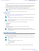
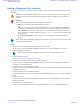
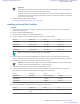

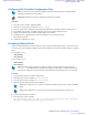


Table Of Contents
- 5827 Exhibit D - User Information
- Tune-Up Procedure
- User Manual
- MANUAL COVER PAGE
- Copyrights
- CMM Labeling and Disclosure Table
- Service Information
- Document History
- Contents
- List of Figures
- List of Tables
- List of Processes
- List of Procedures
- About MTS LiTE, MTS 2 and MTS 4 Installation, Configuration and Basic Service Manual
- MTS Overview
- General Safety
- Radio Frequency Distribution System
- RFDS Theory of Operation
- MTS LiTE and MTS 2 RFDS
- MTS 4 RFDS
- Expansion Cabinet RFDS
- Site Controller
- XHUB Controller
- Base Radio
- Power Supply Unit
- Cooling Fans
- Technical Specifications
- Environmental and Standards Specifications
- Cabinet and Module Specifications
- MTS Cabinets Frequency Range
- Dimensions of the MTS Cabinets
- RF Specifications
- Transmitter Specifications
- Receiver Specifications
- Site Controller Specifications
- Internal GPS Module Input Specifications
- MTS LiTE / MTS 2 Duplexer Specifications
- MTS LiTE / MTS 2 Preselector Specifications
- MTS 4 Duplexer Specifications
- MTS 4 Post Filter Specifications
- MTS 4 Preselector Specifications
- Auto Tune Cavity Combiner (ATCC) Specifications
- Manual Tune Cavity Combiner (MTCC) Specifications
- Hybrid Combiner Specifications
- Base Radio Specifications
- Power Supply Unit Specifications
- XHUB Controller Specifications
- RX Splitter Specifications
- MTS LiTE, MTS 2, and MTS 4 Connectors
- Expansion Options
- MTS 4 Outdoor Enclosure
- Appendix A: Field Replaceable Units (FRUs)
- Appendix B: Planned Maintenance Inspection (PMI)
- Appendix C: Static Precautions and ESD Strap
- Appendix D: TETRA/Dimetra Acronyms

Installing the Cavity Combiner into the Cabinet
Procedure:
1 Switch OFF the Power Supply Unit.
Note: Only applies for Auto Tuned Cavity Combiner (ATCC).
2 Remove the panel in front of where the additional Cavity Combiner is to be assembled.
3 Assemble bracket with 3 M6x10 screws.
4 Attach the DC cable to DC ATCC Out on the Power Supply Unit. Connect it to the DC socket on the control box
on the Cavity Combiner.
Note: Only applies for Auto Tuned Cavity Combiner.
Note: Route the DC cable so it will be placed behind the additional Cavity Combiner.
5 Slide the Cavity Combiner into the cabinet.
6 Fasten the three screws (two on the left and one on the right) that hold the Cavity Combiner onto the brackets of
the cabinet
.
7 Attach the TX cables to the Base Radios.
8 Unplug the TX cable connected to ATCC 1 / TX Out connector and attach the TX Interconnect Harness to the
ATCC 1 / TX Out and ATCC 2 / TX Out connectors. Connect the original cable to the TX Interconnect Harness.
9 Unplug the CAN Bus cable connected to ATCC 1 / CAN2 connector and attach it to ATCC 2 / CAN2 instead.
Action From To
Before Duplexer / CAN Out ATCC 1 / CAN2
After Duplexer / CAN Out ATCC 2 / CAN2
Note: When Manually Tuned Cavity Combiners are used, the CAN Bus is connected directly from
Duplexer or PostFilter / CAN2 connector to Power Supply Unit 2 / CAN1 connector.
10 Connect the CAN Bus cable from the existing Cavity Combiner to the new Cavity Combiner according to the
scheme below:
Part no Cable type From To
3066544B09
CAN Bus cable ATCC 1 / CAN2 ATCC 2 / CAN1
3066544B06
CAN Bus cable ATCC 1 / CAN1 PSU2 / CAN1
Note: If a terminator is situated in the ATCC 1 / CAN1 connector before cabling according to scheme
above, the terminator is removed.
11 Switch ON the Power Supply Unit.
Configuration
When the new Cavity Combiner has been installed, the mapping list needs to be updated with the new TrackID. For
more information, see Updating the Mapping List with the New TrackID on page 256.
Expansion Options |
397
6802800U74-AD | September 2014 |
Send Feedback
Applicant: Motorola Solutions
Equipment Type: ABZ89FC5827 / 109AB-5827
Exhibit D2