
User's Manual

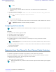


Table Of Contents
- 5827 Exhibit D - User Information
- Tune-Up Procedure
- User Manual
- MANUAL COVER PAGE
- Copyrights
- CMM Labeling and Disclosure Table
- Service Information
- Document History
- Contents
- List of Figures
- List of Tables
- List of Processes
- List of Procedures
- About MTS LiTE, MTS 2 and MTS 4 Installation, Configuration and Basic Service Manual
- MTS Overview
- General Safety
- Radio Frequency Distribution System
- RFDS Theory of Operation
- MTS LiTE and MTS 2 RFDS
- MTS 4 RFDS
- Expansion Cabinet RFDS
- Site Controller
- XHUB Controller
- Base Radio
- Power Supply Unit
- Cooling Fans
- Technical Specifications
- Environmental and Standards Specifications
- Cabinet and Module Specifications
- MTS Cabinets Frequency Range
- Dimensions of the MTS Cabinets
- RF Specifications
- Transmitter Specifications
- Receiver Specifications
- Site Controller Specifications
- Internal GPS Module Input Specifications
- MTS LiTE / MTS 2 Duplexer Specifications
- MTS LiTE / MTS 2 Preselector Specifications
- MTS 4 Duplexer Specifications
- MTS 4 Post Filter Specifications
- MTS 4 Preselector Specifications
- Auto Tune Cavity Combiner (ATCC) Specifications
- Manual Tune Cavity Combiner (MTCC) Specifications
- Hybrid Combiner Specifications
- Base Radio Specifications
- Power Supply Unit Specifications
- XHUB Controller Specifications
- RX Splitter Specifications
- MTS LiTE, MTS 2, and MTS 4 Connectors
- Expansion Options
- MTS 4 Outdoor Enclosure
- Appendix A: Field Replaceable Units (FRUs)
- Appendix B: Planned Maintenance Inspection (PMI)
- Appendix C: Static Precautions and ESD Strap
- Appendix D: TETRA/Dimetra Acronyms

6 Insert the additional Base Radio by aligning the side rails with the appropriate rail guides inside the Base Radio
chassis.
7 Gently push the additional module completely into the Base Radio chassis assembly using the module handle(s).
Be careful not to damage any of the cables previously connected when pushing the Base Radio into position.
8 Secure the additional module using two TORX screws. Tighten the screws to a torque of 2.7 Nm.
9 Connect the Power cables, Ethernet cable, Tx cable and Rx cables to the BR front plate.
Note: If single or dual diversity, use QMA terminator (2866544A01) in unused Rx connectors on Base
Radio(s).
10 Switch ON the Power Supply Unit. You do not need to do this if doing a hotswap.
Configuration
Basic configuration of base radios is needed when additional base radio(s) has been added to the MTS 4 cabinet. This
is described in Configuring and Verifying the Base Radio
on page 213.
Note:
Base radios in the second Module Cage should be configured with <cabinet>:<position> set as
1:3 and 1:4.
Note: For configurations with Manual Tuned Cavity Combiner(s), the MTCC needs to be tuned after
adding additional Base Radio.
In addition to this, the following parameters need to be configured in TESS application:
• Factory password
• Field password
•
Cabinet ID
• Position ID
• Carrier Number (TX/RX frequencies are auto-generated based on Carrier Number setting)
• Default TX Power level
Note: When these parameters have been configured in TESS Application and after the modified
configuration file has been uploaded to the Site Controller, the complete site needs to be reset to implement
the configuration change.
Redundant Site Controller
It is possible to add an additional (redundant) Site Controller to MTS 4. To add a redundant Site Controller, two
module cages must be present in the MTS 4.
Note: If a redundant Site Controller is added to an MTS with an expansion cabinet, a redundant XHUB
must also be added.
Note:
Redundant Site Controller feature is supported on releases:
• R6.0_001.12, MTS 05
• R5.2_002.34, MTS 10
and later.
The additional Site Controller is delivered with the expansion kit that includes required equipment and cables.
Expansion Options |
389
6802800U74-AD | September 2014 |
Send Feedback
Applicant: Motorola Solutions
Equipment Type: ABZ89FC5827 / 109AB-5827
Exhibit D2