
User's Manual
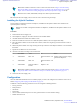


Table Of Contents
- 5827 Exhibit D - User Information
- Tune-Up Procedure
- User Manual
- MANUAL COVER PAGE
- Copyrights
- CMM Labeling and Disclosure Table
- Service Information
- Document History
- Contents
- List of Figures
- List of Tables
- List of Processes
- List of Procedures
- About MTS LiTE, MTS 2 and MTS 4 Installation, Configuration and Basic Service Manual
- MTS Overview
- General Safety
- Radio Frequency Distribution System
- RFDS Theory of Operation
- MTS LiTE and MTS 2 RFDS
- MTS 4 RFDS
- Expansion Cabinet RFDS
- Site Controller
- XHUB Controller
- Base Radio
- Power Supply Unit
- Cooling Fans
- Technical Specifications
- Environmental and Standards Specifications
- Cabinet and Module Specifications
- MTS Cabinets Frequency Range
- Dimensions of the MTS Cabinets
- RF Specifications
- Transmitter Specifications
- Receiver Specifications
- Site Controller Specifications
- Internal GPS Module Input Specifications
- MTS LiTE / MTS 2 Duplexer Specifications
- MTS LiTE / MTS 2 Preselector Specifications
- MTS 4 Duplexer Specifications
- MTS 4 Post Filter Specifications
- MTS 4 Preselector Specifications
- Auto Tune Cavity Combiner (ATCC) Specifications
- Manual Tune Cavity Combiner (MTCC) Specifications
- Hybrid Combiner Specifications
- Base Radio Specifications
- Power Supply Unit Specifications
- XHUB Controller Specifications
- RX Splitter Specifications
- MTS LiTE, MTS 2, and MTS 4 Connectors
- Expansion Options
- MTS 4 Outdoor Enclosure
- Appendix A: Field Replaceable Units (FRUs)
- Appendix B: Planned Maintenance Inspection (PMI)
- Appendix C: Static Precautions and ESD Strap
- Appendix D: TETRA/Dimetra Acronyms

3066553B01 AC Power Cable Junction panel / AC In 2
PSU2 / AC In
3066556B02 Batt Sens cable Junction panel / Bat Temp 2
PSU2 / Battery Temp. Sens.
3066545B01 DC Power Cable BR3 / DC In
PSU2 / DC Out
BR4 / DC In
Site Controller / Power
Note: If Base Radio being added is the second Base Radio in a Module Cage (BR2 or BR4), DC Power
Cable (3066545B01) is already existing in configuration.
12 Connect the RJ45 cable according to the scheme below:
Part no Cable type From To
3066544B06 RJ45 Cable PSU2 / CAN1 CAN socket where terminator is situated (ter-
minator to be removed and replaced by the
cable instead). Could be on a filter or ATCC.
In case of no redundant Site Controller, the
terminator should be placed in PSU 2/ CAN 2
output.
13 Switch ON the Power Supply Unit.
14 Check the LED indicators to verify the PSU is operating correctly.
Configuration
No configuration in itself is needed for the module cage, but the Power Supply Unit needs to be configured and this is
described in Updating the Mapping List with the New PSU TrackID on page 303
.
Installation and configuration of additional Base Radios are described separately in Additional Base Radio for
Existing Module Cage in MTS 4 on page 381.
Furthermore, if an additional Site Controller is ordered as a separate expansion kit, it needs to be installed and
configured, see Redundant Site Controller on page 389.
Additional Base Radio for Existing Module Cage in MTS 4
It is possible to add a Base Radio into an existing module cage of the MTS 4.
Note: The additional Base Radio is delivered with the expansion kit that includes required equipment and
cables.
Expansion Options | 381
6802800U74-AD | September 2014 | Send Feedback
Applicant: Motorola Solutions
Equipment Type: ABZ89FC5827 / 109AB-5827
Exhibit D2