
User's Manual
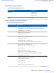

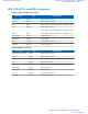


Table Of Contents
- 5827 Exhibit D - User Information
- Tune-Up Procedure
- User Manual
- MANUAL COVER PAGE
- Copyrights
- CMM Labeling and Disclosure Table
- Service Information
- Document History
- Contents
- List of Figures
- List of Tables
- List of Processes
- List of Procedures
- About MTS LiTE, MTS 2 and MTS 4 Installation, Configuration and Basic Service Manual
- MTS Overview
- General Safety
- Radio Frequency Distribution System
- RFDS Theory of Operation
- MTS LiTE and MTS 2 RFDS
- MTS 4 RFDS
- Expansion Cabinet RFDS
- Site Controller
- XHUB Controller
- Base Radio
- Power Supply Unit
- Cooling Fans
- Technical Specifications
- Environmental and Standards Specifications
- Cabinet and Module Specifications
- MTS Cabinets Frequency Range
- Dimensions of the MTS Cabinets
- RF Specifications
- Transmitter Specifications
- Receiver Specifications
- Site Controller Specifications
- Internal GPS Module Input Specifications
- MTS LiTE / MTS 2 Duplexer Specifications
- MTS LiTE / MTS 2 Preselector Specifications
- MTS 4 Duplexer Specifications
- MTS 4 Post Filter Specifications
- MTS 4 Preselector Specifications
- Auto Tune Cavity Combiner (ATCC) Specifications
- Manual Tune Cavity Combiner (MTCC) Specifications
- Hybrid Combiner Specifications
- Base Radio Specifications
- Power Supply Unit Specifications
- XHUB Controller Specifications
- RX Splitter Specifications
- MTS LiTE, MTS 2, and MTS 4 Connectors
- Expansion Options
- MTS 4 Outdoor Enclosure
- Appendix A: Field Replaceable Units (FRUs)
- Appendix B: Planned Maintenance Inspection (PMI)
- Appendix C: Static Precautions and ESD Strap
- Appendix D: TETRA/Dimetra Acronyms

Installing an Additional Base Radio to MTS 2
Procedure:
1 Remove the Blind Plate where the additional Base Radio is to be assembled.
2 Label all new Rx cables with labels included in the expansion kit.
3 Attach the Rx cables to the filters. Connect them according to the scheme below:
# Part no Cable type Label From To
5
3066543B01 Rx cable Rx1 Filter pos 1 / BR2 BR2 / Rx1
6
3066543B01 Rx cable Rx2 Filter pos 2 / BR2 BR2 / Rx2
7
3066543B01 Rx cable Rx3 Filter pos 3 / BR2 BR2 / Rx3
Note: Index numbers in table above refer to cable connections shown in Figure 193: RF Cabling
Diagram for MTS 2 with one TX/RX ant. and up to two RX ant. after Expansion on page 376.
Note: At this stage only connect the cables to the filters.
4 Attach the Tx-cable to the Tx input of the filter in position 2.
Note: At this stage only connect the cable to the filter.
5 Attach the Ethernet cable 3066544B02 to the BR2 connector on the Site Controller. This is illustrated in Figure
194: E1 and Ethernet Cabling Diagram for MTS 2 after Expansion on page 377 as connection #2.
Note: At this stage only connect the cable to the Site Controller. Follow the color scheme displayed on
the Site Controller front panel.
6 Insert the additional Base Radio by aligning the side rails with the appropriate rail guides inside the Base Radio
chassis.
7 Gently push the additional module completely into the Base Radio chassis assembly using the module handle.
Caution: Be careful not to damage any of the cables previously connected when pushing the Base
Radio into position.
8 Secure the additional module using two TORX screws. Tighten the screws to a torque of 2.7 Nm.
9 Connect the Power cables, Ethernet cable, Tx cable and Rx Cables to the BR front plate. Make sure cables are
connected according to scheme below:
# Part number Cable type Label From To
N/A
3066545B01 DC Power Cable N/A PSU / DC Out BR1 / DC IN
BR2 / DC In
SC1 / Power
5
3066543B01 Rx Cable Rx1 Filter pos 1 / BR2 BR2 / Rx1
6
Rx2 Filter pos 2 / BR2 BR2 / Rx2
7
Rx3 Filter pos 3 / BR2 BR2 / Rx3
N/A
3066543B05 Tx Cable N/A Filter pos 2 / Tx BR2 / Tx
2 in A)
3066545B02 Ethernet N/A SC1 / BR2 BR2 / SC1
378 | Expansion Options
Send Feedback | September 2014 | 6802800U74-AD
Applicant: Motorola Solutions
Equipment Type: ABZ89FC5827 / 109AB-5827
Exhibit D2