
User's Manual

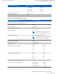


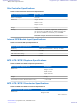
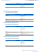
Table Of Contents
- 5827 Exhibit D - User Information
- Tune-Up Procedure
- User Manual
- MANUAL COVER PAGE
- Copyrights
- CMM Labeling and Disclosure Table
- Service Information
- Document History
- Contents
- List of Figures
- List of Tables
- List of Processes
- List of Procedures
- About MTS LiTE, MTS 2 and MTS 4 Installation, Configuration and Basic Service Manual
- MTS Overview
- General Safety
- Radio Frequency Distribution System
- RFDS Theory of Operation
- MTS LiTE and MTS 2 RFDS
- MTS 4 RFDS
- Expansion Cabinet RFDS
- Site Controller
- XHUB Controller
- Base Radio
- Power Supply Unit
- Cooling Fans
- Technical Specifications
- Environmental and Standards Specifications
- Cabinet and Module Specifications
- MTS Cabinets Frequency Range
- Dimensions of the MTS Cabinets
- RF Specifications
- Transmitter Specifications
- Receiver Specifications
- Site Controller Specifications
- Internal GPS Module Input Specifications
- MTS LiTE / MTS 2 Duplexer Specifications
- MTS LiTE / MTS 2 Preselector Specifications
- MTS 4 Duplexer Specifications
- MTS 4 Post Filter Specifications
- MTS 4 Preselector Specifications
- Auto Tune Cavity Combiner (ATCC) Specifications
- Manual Tune Cavity Combiner (MTCC) Specifications
- Hybrid Combiner Specifications
- Base Radio Specifications
- Power Supply Unit Specifications
- XHUB Controller Specifications
- RX Splitter Specifications
- MTS LiTE, MTS 2, and MTS 4 Connectors
- Expansion Options
- MTS 4 Outdoor Enclosure
- Appendix A: Field Replaceable Units (FRUs)
- Appendix B: Planned Maintenance Inspection (PMI)
- Appendix C: Static Precautions and ESD Strap
- Appendix D: TETRA/Dimetra Acronyms

Note: All specifications listed in the following two tables are observed at RF distribution system output
unless stated otherwise.
Table 109: Transmit Specifications – TETRA
Transmitter Specification Value or Range
Pi/4DQPSK Transmitted Power (10, 25, 40
Watts depending on the configuration) measured
at RFDS antenna port:
10 W, 25 W, 40 W
Normal Conditions: +2.0 dB
Extreme Conditions: +3.0/-4.0 dB
Transmitter Power (off/standby)
-36 dBm/-40 dBc
Frequency Stability ± 0.007 ppm
Note: Stability with site reference connected to sta-
tion and locked to GPS.
Base Radio Power Limits
High Power BR: 5W - 80 W
Low Power BR: 2W - 36W
Note: Base Radio Power Limits above are also appli-
cable for 800 MHz.
260 MHz Low Power BR: 2W - 40 W
Transmitter Power Control 12 dB
Carrier Feedthrough -26 dBc
Transmitter Modulation Accuracy 6% RMS/Burst (30% peak/symbol)
Synchronization 1/4 symbol
Adjacent-channel Power due to Modulation
(Normal Conditions)
± 25 kHz
± 50 kHz
± 75 kHz
-60 dBc (800 MHz/ 900 MHz:
-55 dBc)
-70 dBc (800 MHz/ 900 MHz:
-65 dBc)
-70 dBc(800 MHz/ 900 MHz:
-65 dBc)
Adjacent-channel Power due to Modulation (Ex-
treme Conditions)
± 25 kHz
± 50 kHz
± 75 kHz
-50 dBc(800 MHz/ 900 MHz:
-45 dBc)
-60 dBc(800 MHz/ 900 MHz:
-55 dBc)
-60 dBc (800 MHz/ 900 MHz:
-55 dBc)
Adjacent-channel Power due to Switching -50 dBc
Adjacent-channel Power due to Linearization -30 dBc
Tx Conducted Emission
100 - 250 kHz -80 dBc
Table continued…
362 | Technical Specifications
Send Feedback | September 2014 | 6802800U74-AD
Applicant: Motorola Solutions
Equipment Type: ABZ89FC5827 / 109AB-5827
Exhibit D2