
User's Manual

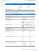


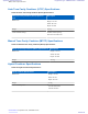
Table Of Contents
- 5827 Exhibit D - User Information
- Tune-Up Procedure
- User Manual
- MANUAL COVER PAGE
- Copyrights
- CMM Labeling and Disclosure Table
- Service Information
- Document History
- Contents
- List of Figures
- List of Tables
- List of Processes
- List of Procedures
- About MTS LiTE, MTS 2 and MTS 4 Installation, Configuration and Basic Service Manual
- MTS Overview
- General Safety
- Radio Frequency Distribution System
- RFDS Theory of Operation
- MTS LiTE and MTS 2 RFDS
- MTS 4 RFDS
- Expansion Cabinet RFDS
- Site Controller
- XHUB Controller
- Base Radio
- Power Supply Unit
- Cooling Fans
- Technical Specifications
- Environmental and Standards Specifications
- Cabinet and Module Specifications
- MTS Cabinets Frequency Range
- Dimensions of the MTS Cabinets
- RF Specifications
- Transmitter Specifications
- Receiver Specifications
- Site Controller Specifications
- Internal GPS Module Input Specifications
- MTS LiTE / MTS 2 Duplexer Specifications
- MTS LiTE / MTS 2 Preselector Specifications
- MTS 4 Duplexer Specifications
- MTS 4 Post Filter Specifications
- MTS 4 Preselector Specifications
- Auto Tune Cavity Combiner (ATCC) Specifications
- Manual Tune Cavity Combiner (MTCC) Specifications
- Hybrid Combiner Specifications
- Base Radio Specifications
- Power Supply Unit Specifications
- XHUB Controller Specifications
- RX Splitter Specifications
- MTS LiTE, MTS 2, and MTS 4 Connectors
- Expansion Options
- MTS 4 Outdoor Enclosure
- Appendix A: Field Replaceable Units (FRUs)
- Appendix B: Planned Maintenance Inspection (PMI)
- Appendix C: Static Precautions and ESD Strap
- Appendix D: TETRA/Dimetra Acronyms

Note:
The first usable TETRA center frequency in each range is 12.5 kHz above the low range and below high
range.
The first usable TEDS center frequency in each range is:
• 12.5 kHz above the low range and below high range for 25 kHz channel
• 25 kHz above the low range and below high range for 50 kHz channel
Note: ETSI Compliance Notice: The Base Radio is only ETSI-compliant when used in conjunction with a
Motorola-supplied RF distribution system (RFDS). The Base Radio shall not be used without a Motorola-
approved RFDS.
Table 107: Auto Tune and Manual Tune Cavity Combining Transmitter-to-Antenna Port
Specifications
Specifications Value or Range
Cavity Combiner Maximum Insertion Loss: 3.9 dB maximum
(@ 150 kHz Channel Spacing, four-channel) 3.5 dB typical
Note: The cavities are factory set for 150 kHz spacing.
Cavities are not tuned to customer frequency and may
be field tuned. Cavity combiner insertion loss is
combiner only.
Duplex Filter Insertion Loss 1.6 dB maximum
1.2 dB typical
Total RFDS Insertion Loss 4.5 - 5.2 dB
150 kHz Channel Spacing, four-channel 5.2 dB typical
250 kHz Channel Spacing, four-channel 4.7 dB typical
250 kHz Channel Spacing, two-channel 4.5 dB typical
Table 108: Hybrid Combining Transmitter-to-Antenna Port Specifications
Specifications Value or Range
Hybrid Combiner Maximum Insertion Loss: 3.3 dB maximum
3.2 dB typical
Duplex Filter Insertion Loss 1.6 dB maximum
1.2 dB typical
Total Hybrid Combiner Insertion Loss 4.9 dB maximum
4.4 dB typical
Input Return Loss 14 dB minimum
>20 dB typical
Antenna-to-PA Isolation 20 dB minimum
Transmitter Specifications
The following tables list the TETRA and TEDS specifications.
Technical Specifications | 361
6802800U74-AD | September 2014 | Send Feedback
Applicant: Motorola Solutions
Equipment Type: ABZ89FC5827 / 109AB-5827
Exhibit D2