
User's Manual


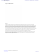

Table Of Contents
- 5827 Exhibit D - User Information
- Tune-Up Procedure
- User Manual
- MANUAL COVER PAGE
- Copyrights
- CMM Labeling and Disclosure Table
- Service Information
- Document History
- Contents
- List of Figures
- List of Tables
- List of Processes
- List of Procedures
- About MTS LiTE, MTS 2 and MTS 4 Installation, Configuration and Basic Service Manual
- MTS Overview
- General Safety
- Radio Frequency Distribution System
- RFDS Theory of Operation
- MTS LiTE and MTS 2 RFDS
- MTS 4 RFDS
- Expansion Cabinet RFDS
- Site Controller
- XHUB Controller
- Base Radio
- Power Supply Unit
- Cooling Fans
- Technical Specifications
- Environmental and Standards Specifications
- Cabinet and Module Specifications
- MTS Cabinets Frequency Range
- Dimensions of the MTS Cabinets
- RF Specifications
- Transmitter Specifications
- Receiver Specifications
- Site Controller Specifications
- Internal GPS Module Input Specifications
- MTS LiTE / MTS 2 Duplexer Specifications
- MTS LiTE / MTS 2 Preselector Specifications
- MTS 4 Duplexer Specifications
- MTS 4 Post Filter Specifications
- MTS 4 Preselector Specifications
- Auto Tune Cavity Combiner (ATCC) Specifications
- Manual Tune Cavity Combiner (MTCC) Specifications
- Hybrid Combiner Specifications
- Base Radio Specifications
- Power Supply Unit Specifications
- XHUB Controller Specifications
- RX Splitter Specifications
- MTS LiTE, MTS 2, and MTS 4 Connectors
- Expansion Options
- MTS 4 Outdoor Enclosure
- Appendix A: Field Replaceable Units (FRUs)
- Appendix B: Planned Maintenance Inspection (PMI)
- Appendix C: Static Precautions and ESD Strap
- Appendix D: TETRA/Dimetra Acronyms

Airflow
MTS LiTE:
The card cage has a clear opening in the bottom front and small holes in the side and back. Ambient airflow enters at
the bottom of the front, back and sides and passes up through the modules. The optimal solution is to allow the air
inlet from all sides. At the top of the card cage there is enough space for the air to distribute and spread before passing
out of the venting grill at the top. If there is nothing in close area to sides, the air can also exit here. The airflow
routing is the same with or without fans.
Figure 183: MTS LiTE Airflow
MTS 2:
The 2 BR card cage has a clear opening in the bottom front and small holes in the side and back. Ambient airflow
enters at the bottom of the front, back and sides and passes up through the modules. The optimal solution is to allow
the air inlet from all sides. At the top of the card cage there is enough space for the air to distribute and spread. It then
passes up through the filter section and out of the venting grill at the top. If there is nothing in close area to sides, the
air can also exit here. The airflow routing is the same with or without fans.
Cooling Fans | 307
6802800U74-AD | September 2014 | Send Feedback
Applicant: Motorola Solutions
Equipment Type: ABZ89FC5827 / 109AB-5827
Exhibit D2