
User's Manual


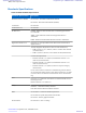
Table Of Contents
- 5827 Exhibit D - User Information
- Tune-Up Procedure
- User Manual
- MANUAL COVER PAGE
- Copyrights
- CMM Labeling and Disclosure Table
- Service Information
- Document History
- Contents
- List of Figures
- List of Tables
- List of Processes
- List of Procedures
- About MTS LiTE, MTS 2 and MTS 4 Installation, Configuration and Basic Service Manual
- MTS Overview
- General Safety
- Radio Frequency Distribution System
- RFDS Theory of Operation
- MTS LiTE and MTS 2 RFDS
- MTS 4 RFDS
- Expansion Cabinet RFDS
- Site Controller
- XHUB Controller
- Base Radio
- Power Supply Unit
- Cooling Fans
- Technical Specifications
- Environmental and Standards Specifications
- Cabinet and Module Specifications
- MTS Cabinets Frequency Range
- Dimensions of the MTS Cabinets
- RF Specifications
- Transmitter Specifications
- Receiver Specifications
- Site Controller Specifications
- Internal GPS Module Input Specifications
- MTS LiTE / MTS 2 Duplexer Specifications
- MTS LiTE / MTS 2 Preselector Specifications
- MTS 4 Duplexer Specifications
- MTS 4 Post Filter Specifications
- MTS 4 Preselector Specifications
- Auto Tune Cavity Combiner (ATCC) Specifications
- Manual Tune Cavity Combiner (MTCC) Specifications
- Hybrid Combiner Specifications
- Base Radio Specifications
- Power Supply Unit Specifications
- XHUB Controller Specifications
- RX Splitter Specifications
- MTS LiTE, MTS 2, and MTS 4 Connectors
- Expansion Options
- MTS 4 Outdoor Enclosure
- Appendix A: Field Replaceable Units (FRUs)
- Appendix B: Planned Maintenance Inspection (PMI)
- Appendix C: Static Precautions and ESD Strap
- Appendix D: TETRA/Dimetra Acronyms

mounted. MTS 4 requires fans for all configurations. There is no need for the fans in MTS 2 for the low power PA
BTS configurations. In other configurations, three fan kits are needed at the bottom of the card cages. There may be a
reliability issue with the fans if operated below -10 °C. At an ambient temperature below -10 °C, the fans are stopped
and restarted again at -8 °C. The fan supply ramps up to 24 V output for a few seconds in all start up situations.
PSU Fan Control
The Power Supply Unit (PSU) contains three fan supply outputs with LED indicators.
Three fan connector outputs supply three fan kits with two fans connected in parallel in each fan tray.
The FAN output specifications are:
• Output Voltage: from 12 to 24 VDC ± 5 %
• Output Current: 1 A for each fan connector output
The fans supply output voltage is linear dependent on the total power delivered by the PSU and the ambient
temperature. The fan supply starts with 24 V output for a few seconds.
For PSU LED indications, see
PSU LED Indicators on page 299.
There are several MMI commands which control the fans:
• psu <PSU number> get fan_voltage
• psu <PSU number> set fan_speed
• psu <PSU number> get fan_speed
• psu <PSU number> set fan_config
• psu <PSU number> get fan_config
• psu <PSU number> start_fan
For description of the PSU fan commands, see the MTS Man Machine Interface Commands manual.
Alarms and Controls Available Through PSU CAN Bus Interface
The fan alarms available through the CAN Bus:
Fan 1 alarm
Fan 1 not operating, PSU received a High signal (open collector) from fan tray 1 through fan connector 1.
Fan 2 alarm
Fan 2 not operating, PSU received a high signal (open collector) from fan tray 2 through fan connector 2.
Fan 3 alarm
Fan 3 not operating, PSU received a high signal (open collector) from fan tray 3 through fan connector 3.
The fans controls available through the CAN Bus:
No Fan 1
Prevents Fan 1 alarm (and associated LED) when no fan 1 is configured.
No Fan 2
Prevents Fan 2 alarm (and associated LED) when no fan 2 is configured.
No Fan 3
Prevents Fan 3 alarm (and associated LED) when no fan 3 is configured.
306 | Cooling Fans
Send Feedback | September 2014 | 6802800U74-AD
Applicant: Motorola Solutions
Equipment Type: ABZ89FC5827 / 109AB-5827
Exhibit D2