
User's Manual
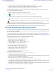

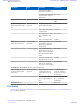
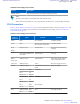
Table Of Contents
- 5827 Exhibit D - User Information
- Tune-Up Procedure
- User Manual
- MANUAL COVER PAGE
- Copyrights
- CMM Labeling and Disclosure Table
- Service Information
- Document History
- Contents
- List of Figures
- List of Tables
- List of Processes
- List of Procedures
- About MTS LiTE, MTS 2 and MTS 4 Installation, Configuration and Basic Service Manual
- MTS Overview
- General Safety
- Radio Frequency Distribution System
- RFDS Theory of Operation
- MTS LiTE and MTS 2 RFDS
- MTS 4 RFDS
- Expansion Cabinet RFDS
- Site Controller
- XHUB Controller
- Base Radio
- Power Supply Unit
- Cooling Fans
- Technical Specifications
- Environmental and Standards Specifications
- Cabinet and Module Specifications
- MTS Cabinets Frequency Range
- Dimensions of the MTS Cabinets
- RF Specifications
- Transmitter Specifications
- Receiver Specifications
- Site Controller Specifications
- Internal GPS Module Input Specifications
- MTS LiTE / MTS 2 Duplexer Specifications
- MTS LiTE / MTS 2 Preselector Specifications
- MTS 4 Duplexer Specifications
- MTS 4 Post Filter Specifications
- MTS 4 Preselector Specifications
- Auto Tune Cavity Combiner (ATCC) Specifications
- Manual Tune Cavity Combiner (MTCC) Specifications
- Hybrid Combiner Specifications
- Base Radio Specifications
- Power Supply Unit Specifications
- XHUB Controller Specifications
- RX Splitter Specifications
- MTS LiTE, MTS 2, and MTS 4 Connectors
- Expansion Options
- MTS 4 Outdoor Enclosure
- Appendix A: Field Replaceable Units (FRUs)
- Appendix B: Planned Maintenance Inspection (PMI)
- Appendix C: Static Precautions and ESD Strap
- Appendix D: TETRA/Dimetra Acronyms

Name of
Connector
Type To/From Comment
Pin 1 -Vfan
Pin 1 -Vfan
Pin 1 Alarm
Fan 2 MOLEX (4 pin, male) Fan 2 DC supply for Fan 2
Pin 1 +Vfan
Pin 1 -Vfan
Pin 1 -Vfan
Pin 1 Alarm
Fan 3 MOLEX (4 pin, male)
Fan 3 DC supply for Fan 3
Pin 1 +Vfan
Pin 1 -Vfan
Pin 1 -Vfan
Pin 1 Alarm
Replacing the Power Supply Unit (PSU)
See the PSU power up sequence in Powering Up the MTS on page 127.
For a list of available FRUs, see Field Replaceable Units (FRUs) on page 405.
Process:
1 Remove the PSU, see
Removing the Power Supply Unit (PSU) on page 302.
2 Install the Power Supply Unit into the cabinet, see Installing the Power Supply Unit (PSU) on page 302.
3 Update the mapping list with the new unit TrackID, see Updating the Mapping List with the New PSU TrackID on
page 303.
Removing the Power Supply Unit (PSU)
Procedure:
1 Switch OFF the Power Supply Unit.
Warning: Make sure that the facility power outlet is off to prevent accidental contact with high energy
and injury to personnel.
2 Remove all cables.
3 Remove two M4x10 Torx 20 screws which secure the PSU front panel to the module cage. Save screws and
washers for reuse. The washers are required in Installing the Power Supply Unit (PSU) on page 302,
step 2.
4 Pull out the Power Supply Unit from the module cage.
Installing the Power Supply Unit (PSU)
Procedure:
1 Place the Power Supply Unit on the slide rails in the module cage and push it to the back.
2 Secure the Power Supply Unit to the module cage with the two M4x10 Torx 20 screws.
302 | Power Supply Unit
Send Feedback | September 2014 | 6802800U74-AD
Applicant: Motorola Solutions
Equipment Type: ABZ89FC5827 / 109AB-5827
Exhibit D2