
User's Manual
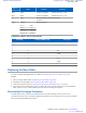
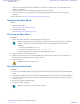
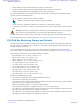

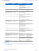
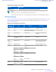
Table Of Contents
- 5827 Exhibit D - User Information
- Tune-Up Procedure
- User Manual
- MANUAL COVER PAGE
- Copyrights
- CMM Labeling and Disclosure Table
- Service Information
- Document History
- Contents
- List of Figures
- List of Tables
- List of Processes
- List of Procedures
- About MTS LiTE, MTS 2 and MTS 4 Installation, Configuration and Basic Service Manual
- MTS Overview
- General Safety
- Radio Frequency Distribution System
- RFDS Theory of Operation
- MTS LiTE and MTS 2 RFDS
- MTS 4 RFDS
- Expansion Cabinet RFDS
- Site Controller
- XHUB Controller
- Base Radio
- Power Supply Unit
- Cooling Fans
- Technical Specifications
- Environmental and Standards Specifications
- Cabinet and Module Specifications
- MTS Cabinets Frequency Range
- Dimensions of the MTS Cabinets
- RF Specifications
- Transmitter Specifications
- Receiver Specifications
- Site Controller Specifications
- Internal GPS Module Input Specifications
- MTS LiTE / MTS 2 Duplexer Specifications
- MTS LiTE / MTS 2 Preselector Specifications
- MTS 4 Duplexer Specifications
- MTS 4 Post Filter Specifications
- MTS 4 Preselector Specifications
- Auto Tune Cavity Combiner (ATCC) Specifications
- Manual Tune Cavity Combiner (MTCC) Specifications
- Hybrid Combiner Specifications
- Base Radio Specifications
- Power Supply Unit Specifications
- XHUB Controller Specifications
- RX Splitter Specifications
- MTS LiTE, MTS 2, and MTS 4 Connectors
- Expansion Options
- MTS 4 Outdoor Enclosure
- Appendix A: Field Replaceable Units (FRUs)
- Appendix B: Planned Maintenance Inspection (PMI)
- Appendix C: Static Precautions and ESD Strap
- Appendix D: TETRA/Dimetra Acronyms

Table 90: Power Supply Unit Controls
Control Description
ON/OFF Switch This switch disconnects DC outputs and charging currents.
Note:
When the power switch is turned off the PSU still consumes 2 mA.
If left connected to the battery for a very long time with no mains power, it could discharge the battery.
PSU Connectors
Table 91: Power Supply Unit Connectors on page 301 lists and describes the PSU connectors and Figure 181: PSU
Front Panel
on page 299 shows their position. For more information on PSU cabling, see Interconnection and
Internal Cabling on page 135.
Table 91: Power Supply Unit Connectors
Name of
Connector
Type To/From Comment
CAN1 RJ45 Site Controller CAN Bus interface
CAN2 RJ45
Duplexer/ Post Filter/ ATCC/
Site Controller/ Terminator
CAN Bus interface
DC In
Battery
Phoenix (2 pin) Junction Panel DC input and backup battery
charging
AC In
IEC (high temperature ver-
sion, male)
Junction Panel AC input
Battery
Temp. Sens.
MOLEX (2 pin) Junction Panel Connection with the backup
battery temperature sensor
ATCC Out MOLEX (2 pin) ATCC DC power supply for ATCC
DC Out MOLEX (14 pin) 2 Base Radios and Site Con-
troller
DC power supply
Pin 1 - 3 GND Base Radio
Pin 8 +7 V
Pin 10 - 11 +28.5 V
Pin 4 - 6 GND Base Radio
Pin 9 +7 V
Pin 12 - 13 +28.5 V
Pin 7 GND Site Controller
Pin 14 +28.5 V
Fan 1 MOLEX (4 pin, male) Fan 1 DC supply for Fan 1
Pin 1 +Vfan
Table continued…
Power Supply Unit | 301
6802800U74-AD | September 2014 | Send Feedback
Applicant: Motorola Solutions
Equipment Type: ABZ89FC5827 / 109AB-5827
Exhibit D2