
User's Manual
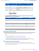
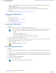

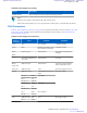
Table Of Contents
- 5827 Exhibit D - User Information
- Tune-Up Procedure
- User Manual
- MANUAL COVER PAGE
- Copyrights
- CMM Labeling and Disclosure Table
- Service Information
- Document History
- Contents
- List of Figures
- List of Tables
- List of Processes
- List of Procedures
- About MTS LiTE, MTS 2 and MTS 4 Installation, Configuration and Basic Service Manual
- MTS Overview
- General Safety
- Radio Frequency Distribution System
- RFDS Theory of Operation
- MTS LiTE and MTS 2 RFDS
- MTS 4 RFDS
- Expansion Cabinet RFDS
- Site Controller
- XHUB Controller
- Base Radio
- Power Supply Unit
- Cooling Fans
- Technical Specifications
- Environmental and Standards Specifications
- Cabinet and Module Specifications
- MTS Cabinets Frequency Range
- Dimensions of the MTS Cabinets
- RF Specifications
- Transmitter Specifications
- Receiver Specifications
- Site Controller Specifications
- Internal GPS Module Input Specifications
- MTS LiTE / MTS 2 Duplexer Specifications
- MTS LiTE / MTS 2 Preselector Specifications
- MTS 4 Duplexer Specifications
- MTS 4 Post Filter Specifications
- MTS 4 Preselector Specifications
- Auto Tune Cavity Combiner (ATCC) Specifications
- Manual Tune Cavity Combiner (MTCC) Specifications
- Hybrid Combiner Specifications
- Base Radio Specifications
- Power Supply Unit Specifications
- XHUB Controller Specifications
- RX Splitter Specifications
- MTS LiTE, MTS 2, and MTS 4 Connectors
- Expansion Options
- MTS 4 Outdoor Enclosure
- Appendix A: Field Replaceable Units (FRUs)
- Appendix B: Planned Maintenance Inspection (PMI)
- Appendix C: Static Precautions and ESD Strap
- Appendix D: TETRA/Dimetra Acronyms

LED Name Color Condition Indications
and the source voltage
drops below 43VDC ±3%
No source connected to DC
input or the DC voltage is
below 40,5V
Red - solid
AC operations only mode LED off or Green –
solid
DC Out / Temp. (DC out-
put and temperature indica-
tor)
dual color LED:
green/red
DC output voltages are
present and within limits
Green - solid
One or more of the output
voltages failed
Red - solid
Over temperature is detect-
ed, 5 -10 C before shut-
down
Red - flashes
PSU is in standby mode LED off
Fan # Status (Fan indicator
# (near fan connector #))
dual color LED:
green/red
Fan # programmed to oper-
ate and Fan # connected,
operating and fan failure
signal is high
Green - solid
Fan # connected but pro-
grammed not to operate or
Fan # voltage is out of lim-
its or the fan failure signal
is low
Red - solid
Fan # not connected and
programmed not to operate
No light
Fan # not connected, at
start up, but should have
been as per CAN command
Red - flashing
LED indication in boot mode (firmware update through CAN)
Upper 3 LEDs (AC In Sta-
tus, DC In Status and DC
Out/ Temp.)
3 dual color LEDs:
green/red
only boot loader is running
(meaning that the boot
loader waits for an .exe
file)
3 LEDs blinking to-
gether: R (red) R R ->
G (green) G G, with 1
Hz frequency
boot loader is loading a
new hex file: (loading sta-
tus)
R R G -> R G R-> G R
R->... (circulating
green LED)
Fan indicators 1 to 3
always Red - solid
PSU Switch
Table 90: Power Supply Unit Controls on page 301 describes the PSU switch and Figure 181: PSU Front Panel on
page 299 shows its position.
300
| Power Supply Unit
Send Feedback | September 2014 | 6802800U74-AD
Applicant: Motorola Solutions
Equipment Type: ABZ89FC5827 / 109AB-5827
Exhibit D2