
User's Manual
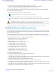

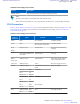
Table Of Contents
- 5827 Exhibit D - User Information
- Tune-Up Procedure
- User Manual
- MANUAL COVER PAGE
- Copyrights
- CMM Labeling and Disclosure Table
- Service Information
- Document History
- Contents
- List of Figures
- List of Tables
- List of Processes
- List of Procedures
- About MTS LiTE, MTS 2 and MTS 4 Installation, Configuration and Basic Service Manual
- MTS Overview
- General Safety
- Radio Frequency Distribution System
- RFDS Theory of Operation
- MTS LiTE and MTS 2 RFDS
- MTS 4 RFDS
- Expansion Cabinet RFDS
- Site Controller
- XHUB Controller
- Base Radio
- Power Supply Unit
- Cooling Fans
- Technical Specifications
- Environmental and Standards Specifications
- Cabinet and Module Specifications
- MTS Cabinets Frequency Range
- Dimensions of the MTS Cabinets
- RF Specifications
- Transmitter Specifications
- Receiver Specifications
- Site Controller Specifications
- Internal GPS Module Input Specifications
- MTS LiTE / MTS 2 Duplexer Specifications
- MTS LiTE / MTS 2 Preselector Specifications
- MTS 4 Duplexer Specifications
- MTS 4 Post Filter Specifications
- MTS 4 Preselector Specifications
- Auto Tune Cavity Combiner (ATCC) Specifications
- Manual Tune Cavity Combiner (MTCC) Specifications
- Hybrid Combiner Specifications
- Base Radio Specifications
- Power Supply Unit Specifications
- XHUB Controller Specifications
- RX Splitter Specifications
- MTS LiTE, MTS 2, and MTS 4 Connectors
- Expansion Options
- MTS 4 Outdoor Enclosure
- Appendix A: Field Replaceable Units (FRUs)
- Appendix B: Planned Maintenance Inspection (PMI)
- Appendix C: Static Precautions and ESD Strap
- Appendix D: TETRA/Dimetra Acronyms

Charge voltage decreases with increasing battery temperature with the ratio of -72mV/C, starting with 56.88VDC
+/-1% at -10 °C and ending with 52.56 VDC +/-1% at +50 °C
The PSU charges the backup batteries on the following conditions (DC In Status LED is flashing fast (0.5 s) red-
green):
• Temperature range*:-10 °C to +50 °C
• Battery Low Voltage start up:40V -5%/+1%
•
Battery Low Voltage Warning:43V ±2%
The PSU stops charging the backup battery on the following conditions:
• Internal PSU temperature:> 100 °C
• Battery Temperature*: -12.5 °C
• Battery Temperature*:> 53 °C
*When a temperature sensor is connected to the battery and PSU. If the battery sensor is not connected the battery
will be charged with 54.24 ±1%VDC as if the battery temperature was 25 °C. The battery temperature monitored
through CAN Bus will show 100 °C.
Fans
The PSU supplies fans, which are located in the fan trays under the module cage. For more information on fans, see
Cooling Fans on page 305. The PSU DC output voltage dedicated for fans is 12 to 24VDC and the output current is
1 A for each fan.
Three fan output connectors supply three fan trays with two fans connected in parallel in each fan tray.
Fan supply output voltage can be automatically regulated as a function of PSU internal (ambient) temperature and its
output power. Fan supply output voltage can also be controlled by the CAN Bus in 7 steps from 24V to 12V. The
highest value wins – automatic control versus CAN control.
At an ambient temperature below -10 °C the fans are stopped and restarted again at -8 °C. The fan supply ramps up to
24V output for a few seconds in all start up situations.
Power Supply Unit (PSU) Indicators, Switches, and Connectors
The following figure shows the positions of indicators, switches and connectors on the PSU front panel.
298 | Power Supply Unit
Send Feedback | September 2014 | 6802800U74-AD
Applicant: Motorola Solutions
Equipment Type: ABZ89FC5827 / 109AB-5827
Exhibit D2