
User's Manual
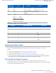

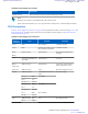
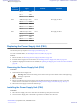
Table Of Contents
- 5827 Exhibit D - User Information
- Tune-Up Procedure
- User Manual
- MANUAL COVER PAGE
- Copyrights
- CMM Labeling and Disclosure Table
- Service Information
- Document History
- Contents
- List of Figures
- List of Tables
- List of Processes
- List of Procedures
- About MTS LiTE, MTS 2 and MTS 4 Installation, Configuration and Basic Service Manual
- MTS Overview
- General Safety
- Radio Frequency Distribution System
- RFDS Theory of Operation
- MTS LiTE and MTS 2 RFDS
- MTS 4 RFDS
- Expansion Cabinet RFDS
- Site Controller
- XHUB Controller
- Base Radio
- Power Supply Unit
- Cooling Fans
- Technical Specifications
- Environmental and Standards Specifications
- Cabinet and Module Specifications
- MTS Cabinets Frequency Range
- Dimensions of the MTS Cabinets
- RF Specifications
- Transmitter Specifications
- Receiver Specifications
- Site Controller Specifications
- Internal GPS Module Input Specifications
- MTS LiTE / MTS 2 Duplexer Specifications
- MTS LiTE / MTS 2 Preselector Specifications
- MTS 4 Duplexer Specifications
- MTS 4 Post Filter Specifications
- MTS 4 Preselector Specifications
- Auto Tune Cavity Combiner (ATCC) Specifications
- Manual Tune Cavity Combiner (MTCC) Specifications
- Hybrid Combiner Specifications
- Base Radio Specifications
- Power Supply Unit Specifications
- XHUB Controller Specifications
- RX Splitter Specifications
- MTS LiTE, MTS 2, and MTS 4 Connectors
- Expansion Options
- MTS 4 Outdoor Enclosure
- Appendix A: Field Replaceable Units (FRUs)
- Appendix B: Planned Maintenance Inspection (PMI)
- Appendix C: Static Precautions and ESD Strap
- Appendix D: TETRA/Dimetra Acronyms

Name of
Connector
Type To/From Comment
RX2 QMA Preselector/ Duplexer RF RX signal and +7 V dc
RX3 QMA Preselector/ Duplexer RF RX signal and +7 V dc
Tx QMA Hybrid Combiner/ Cavity
Combiner
RF TX signal
Power MOLEX Power Supply Unit
Pin 1 - 3 GND
Pin 4 +7 V
Pin 6 - 7 +28.5 V
Pin 5, 8 - 14 not used
Table 88: Base Radio – Service Cable Pinouts
RJ45 PIN D-SUB 9 FEMALE PIN Description
1
2
3
4 3 Rx
5 5 GND
6
7 2 Tx
8 5 GND
9
Replacing the Base Radio
For a list of available Field Replaceable Units (FRUs), see Field Replaceable Units (FRUs) on page 405.
Process:
1 Remove the Base Radio module, see Removing the Base Radio
on page 294.
2 Reinstall the new Base Radio, see Reinstalling the Base Radio on page 294.
3 Perform the procedures from the Configuring and Verifying the Base Radio on page 213 section.
4 If Encryption and/or Authentication is used, see MTS LiTE, MTS 2, and MTS 4 Restoration manual (for DIPS/
DIPC systems) or Service Manual (DIPM system) for details on loading Ki's into MTS.
Electrostatic Discharge Precaution
The Base Radio circuitry contains many CMOS and other electrostatic discharge sensitive devices. Take
precautionary measures to prevent damage of Base Radio modules by static discharge when servicing the equipment.
Observe the following additional precautions:
Base Radio | 293
6802800U74-AD | September 2014 |
Send Feedback
Applicant: Motorola Solutions
Equipment Type: ABZ89FC5827 / 109AB-5827
Exhibit D2