
User's Manual

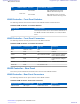


Table Of Contents
- 5827 Exhibit D - User Information
- Tune-Up Procedure
- User Manual
- MANUAL COVER PAGE
- Copyrights
- CMM Labeling and Disclosure Table
- Service Information
- Document History
- Contents
- List of Figures
- List of Tables
- List of Processes
- List of Procedures
- About MTS LiTE, MTS 2 and MTS 4 Installation, Configuration and Basic Service Manual
- MTS Overview
- General Safety
- Radio Frequency Distribution System
- RFDS Theory of Operation
- MTS LiTE and MTS 2 RFDS
- MTS 4 RFDS
- Expansion Cabinet RFDS
- Site Controller
- XHUB Controller
- Base Radio
- Power Supply Unit
- Cooling Fans
- Technical Specifications
- Environmental and Standards Specifications
- Cabinet and Module Specifications
- MTS Cabinets Frequency Range
- Dimensions of the MTS Cabinets
- RF Specifications
- Transmitter Specifications
- Receiver Specifications
- Site Controller Specifications
- Internal GPS Module Input Specifications
- MTS LiTE / MTS 2 Duplexer Specifications
- MTS LiTE / MTS 2 Preselector Specifications
- MTS 4 Duplexer Specifications
- MTS 4 Post Filter Specifications
- MTS 4 Preselector Specifications
- Auto Tune Cavity Combiner (ATCC) Specifications
- Manual Tune Cavity Combiner (MTCC) Specifications
- Hybrid Combiner Specifications
- Base Radio Specifications
- Power Supply Unit Specifications
- XHUB Controller Specifications
- RX Splitter Specifications
- MTS LiTE, MTS 2, and MTS 4 Connectors
- Expansion Options
- MTS 4 Outdoor Enclosure
- Appendix A: Field Replaceable Units (FRUs)
- Appendix B: Planned Maintenance Inspection (PMI)
- Appendix C: Static Precautions and ESD Strap
- Appendix D: TETRA/Dimetra Acronyms

# LED/Port name Type Controlled by Indication
• AMBER: BR is keyed without serv-
ice
• GREEN: BR is keyed
LED 2 Aux Red/Green
SW
• OFF: No alarms
• AMBER: not used
• RED: not used
LED 3 Status Red/Green SW Red LED will
turn on before SW
change any indi-
cation
BR status:
• OFF: Status unknown, power off
• GREEN: BRC main application is
running
• AMBER: Waiting for SWDL this is
where the BR will wait if no Site
Controller is present
• RED: SW not started, power on
LED 4
BR Alarm Red/Green
SW
• OFF: No alarms
• AMBER: BR minor alarm: PA, Ex-
citer, RX, BRC Reduced perform-
ance
• RED: BR failed: PA, Exciter, RX,
BRC
LED5 SC 1 Green HW, Enet IC
• OFF: Ethernet link not present
• GREEN: Ethernet link present
LED6 SC 1 Yellow HW, Enet IC
• OFF: Ethernet activity not present
• YELLOW: Ethernet activity present
LED7 SC 2 Green HW, Enet IC
• OFF: Ethernet link not present
• GREEN: Ethernet link present
LED8 SC 2 Yellow HW, Enet IC
• OFF: Ethernet activity not present
• YELLOW: Ethernet activity present
Table 87: Base Radio – Connectors
Name of
Connector
Type To/From Comment
SC1 RJ45 Site Controller Ethernet/CP2 interface
SC2 RJ45
Site Controller Ethernet/CP2 interface
Service RJ45 BRC Provides service access. See Table
88: Base Radio – Service Cable
Pinouts on page 293 for service ca-
ble pinout information.
RX1 QMA Preselector/ Duplexer RF RX signal and +7 V dcl
Table continued…
292 | Base Radio
Send Feedback | September 2014 | 6802800U74-AD
Applicant: Motorola Solutions
Equipment Type: ABZ89FC5827 / 109AB-5827
Exhibit D2