
User's Manual


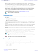


Table Of Contents
- 5827 Exhibit D - User Information
- Tune-Up Procedure
- User Manual
- MANUAL COVER PAGE
- Copyrights
- CMM Labeling and Disclosure Table
- Service Information
- Document History
- Contents
- List of Figures
- List of Tables
- List of Processes
- List of Procedures
- About MTS LiTE, MTS 2 and MTS 4 Installation, Configuration and Basic Service Manual
- MTS Overview
- General Safety
- Radio Frequency Distribution System
- RFDS Theory of Operation
- MTS LiTE and MTS 2 RFDS
- MTS 4 RFDS
- Expansion Cabinet RFDS
- Site Controller
- XHUB Controller
- Base Radio
- Power Supply Unit
- Cooling Fans
- Technical Specifications
- Environmental and Standards Specifications
- Cabinet and Module Specifications
- MTS Cabinets Frequency Range
- Dimensions of the MTS Cabinets
- RF Specifications
- Transmitter Specifications
- Receiver Specifications
- Site Controller Specifications
- Internal GPS Module Input Specifications
- MTS LiTE / MTS 2 Duplexer Specifications
- MTS LiTE / MTS 2 Preselector Specifications
- MTS 4 Duplexer Specifications
- MTS 4 Post Filter Specifications
- MTS 4 Preselector Specifications
- Auto Tune Cavity Combiner (ATCC) Specifications
- Manual Tune Cavity Combiner (MTCC) Specifications
- Hybrid Combiner Specifications
- Base Radio Specifications
- Power Supply Unit Specifications
- XHUB Controller Specifications
- RX Splitter Specifications
- MTS LiTE, MTS 2, and MTS 4 Connectors
- Expansion Options
- MTS 4 Outdoor Enclosure
- Appendix A: Field Replaceable Units (FRUs)
- Appendix B: Planned Maintenance Inspection (PMI)
- Appendix C: Static Precautions and ESD Strap
- Appendix D: TETRA/Dimetra Acronyms

On the front panel, there is a DC power input, three parallel receiver (RX) inputs, a high power transmitter output
signal from the power amplifier, a service port, two interfaces to the Site Controllers, and LED indicators. For more
information on the LED indicators, see Table 86: Base Radio – LED Indicators on page 291.
The following figure shows an overall block diagram of the Base Radio.
Figure 177: Base Radio – Functional Block Diagram
Upon the power-up, BRC bootloader begins to download application code from SC over the Ethernet LAN. After
successful download, the code is executed. Once the BRC application is started, it gets configuration parameters from
SC. The configured BRC application allows the Base Radio to perform call processing functions.
Should any alarm conditions arise during BRC application, operation, they are reported to SC over Ethernet LAN.
Alarm conditions may also be verified locally through the Service Access port linked to a service computer using the
get alarms MMI command.
The Base Radio operates in a TDMA (Time Division Multiple Access) mode. This mode, combined with voice
compression techniques, provides an increased channel capacity ratio of as much as 4 to 1. Both the receive and
transmit signals of the Base Radio are divided into four individual timeslots. Each receive slot has a corresponding
transmit slot; this pair of slots comprises a logical RF channel.
The Base Radio uses single, dual, and triple diversity reception for increased talkback coverage area and improved
quality. The Transceiver contains a three-branch receiver section in which all receivers are used for triple diversity
reception.
Base Radio | 289
6802800U74-AD | September 2014 | Send Feedback
Applicant: Motorola Solutions
Equipment Type: ABZ89FC5827 / 109AB-5827
Exhibit D2