
User's Manual

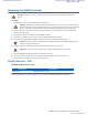

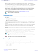


Table Of Contents
- 5827 Exhibit D - User Information
- Tune-Up Procedure
- User Manual
- MANUAL COVER PAGE
- Copyrights
- CMM Labeling and Disclosure Table
- Service Information
- Document History
- Contents
- List of Figures
- List of Tables
- List of Processes
- List of Procedures
- About MTS LiTE, MTS 2 and MTS 4 Installation, Configuration and Basic Service Manual
- MTS Overview
- General Safety
- Radio Frequency Distribution System
- RFDS Theory of Operation
- MTS LiTE and MTS 2 RFDS
- MTS 4 RFDS
- Expansion Cabinet RFDS
- Site Controller
- XHUB Controller
- Base Radio
- Power Supply Unit
- Cooling Fans
- Technical Specifications
- Environmental and Standards Specifications
- Cabinet and Module Specifications
- MTS Cabinets Frequency Range
- Dimensions of the MTS Cabinets
- RF Specifications
- Transmitter Specifications
- Receiver Specifications
- Site Controller Specifications
- Internal GPS Module Input Specifications
- MTS LiTE / MTS 2 Duplexer Specifications
- MTS LiTE / MTS 2 Preselector Specifications
- MTS 4 Duplexer Specifications
- MTS 4 Post Filter Specifications
- MTS 4 Preselector Specifications
- Auto Tune Cavity Combiner (ATCC) Specifications
- Manual Tune Cavity Combiner (MTCC) Specifications
- Hybrid Combiner Specifications
- Base Radio Specifications
- Power Supply Unit Specifications
- XHUB Controller Specifications
- RX Splitter Specifications
- MTS LiTE, MTS 2, and MTS 4 Connectors
- Expansion Options
- MTS 4 Outdoor Enclosure
- Appendix A: Field Replaceable Units (FRUs)
- Appendix B: Planned Maintenance Inspection (PMI)
- Appendix C: Static Precautions and ESD Strap
- Appendix D: TETRA/Dimetra Acronyms

The Base Radio provides reliable digital radio capabilities in a compact software-controlled design. High channel
capacity is provided through voice compression techniques and Time Division Multiplexing (TDM).
On the Base Radio front panel there are connectors and indicators. The indicators provide a means for monitoring
various status and operating conditions of the Base Radio, and also aid in isolating failures. For more information on
Base Radio indicators and connectors, see Base Radio – Indicators and Connectors on page 291 in this chapter.
Base Radio – Theory of Operation
The Base Radio (BR) provides reliable digital communications capabilities. Each Base Radio contains the following
subcomponents:
• Transceiver consisting of a Base Radio Controller, a triple receiver, and an exciter
• Power Amplifier (PA)
In the MTS 2 and 4, the Base Radio (BR) operates in conjunction with the Site Controller (SC) through a properly
terminated 100Base-T Ethernet link.
Figure 176: Base Radio Front Panel
288 | Base Radio
Send Feedback | September 2014 | 6802800U74-AD
Applicant: Motorola Solutions
Equipment Type: ABZ89FC5827 / 109AB-5827
Exhibit D2