
User's Manual

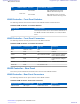


Table Of Contents
- 5827 Exhibit D - User Information
- Tune-Up Procedure
- User Manual
- MANUAL COVER PAGE
- Copyrights
- CMM Labeling and Disclosure Table
- Service Information
- Document History
- Contents
- List of Figures
- List of Tables
- List of Processes
- List of Procedures
- About MTS LiTE, MTS 2 and MTS 4 Installation, Configuration and Basic Service Manual
- MTS Overview
- General Safety
- Radio Frequency Distribution System
- RFDS Theory of Operation
- MTS LiTE and MTS 2 RFDS
- MTS 4 RFDS
- Expansion Cabinet RFDS
- Site Controller
- XHUB Controller
- Base Radio
- Power Supply Unit
- Cooling Fans
- Technical Specifications
- Environmental and Standards Specifications
- Cabinet and Module Specifications
- MTS Cabinets Frequency Range
- Dimensions of the MTS Cabinets
- RF Specifications
- Transmitter Specifications
- Receiver Specifications
- Site Controller Specifications
- Internal GPS Module Input Specifications
- MTS LiTE / MTS 2 Duplexer Specifications
- MTS LiTE / MTS 2 Preselector Specifications
- MTS 4 Duplexer Specifications
- MTS 4 Post Filter Specifications
- MTS 4 Preselector Specifications
- Auto Tune Cavity Combiner (ATCC) Specifications
- Manual Tune Cavity Combiner (MTCC) Specifications
- Hybrid Combiner Specifications
- Base Radio Specifications
- Power Supply Unit Specifications
- XHUB Controller Specifications
- RX Splitter Specifications
- MTS LiTE, MTS 2, and MTS 4 Connectors
- Expansion Options
- MTS 4 Outdoor Enclosure
- Appendix A: Field Replaceable Units (FRUs)
- Appendix B: Planned Maintenance Inspection (PMI)
- Appendix C: Static Precautions and ESD Strap
- Appendix D: TETRA/Dimetra Acronyms

Replacing the XHUB Controller
Warning: See Static Precautions and ESD Strap on page 419 before proceeding with replacement
process.
Procedure:
1 Disconnect the power cables to the MTS Power Supply Units.
Warning: Shock Hazard. The MTS contains dangerous voltages, which can cause electrical shock or
damage to equipment. Turn off the MTS and remove the power cabling before servicing this equipment.
Make sure all power is off to prevent accidental contact with high energy and injury to personnel.
2 Wear an ESD strap and connect its cable to a verified good ground. This strap must be worn to prevent ESD
damage to any components.
3 Tag and disconnect all other cabling from the XHUB Controller.
4 Loosen the two M4X10 captive screws securing the XHUB Controller to the chassis.
5 Use handle, and gently slide the XHUB Controller from the slot, removing it from the chassis.
Important: There are cables connected at rear of the XHUB. Slide out the XHUB carefully, tag and
disconnect ribbon cables at the rear.
6 Install the replacement XHUB Controller. Use handle to slide the unit into the chassis.
Important: Connect the ribbon cables at the rear before sliding the unit in to the chassis.
7 Secure the XHUB Controller in the chassis with the captive screws.
8 Reconnect all other cabling to the unit as tagged during the removal except the power cables.
9 Reconnect the power cables to the MTS Power Supply Units.
XHUB Controller – FRU
Table 85: XHUB Controller - FRU
Kit Number Description
GMLN4689A XHUB MTS-EXP Controller
See Planned Maintenance Inspection (PMI) on page 417 for list of Periodic Maintenance Inspections.
XHUB Controller |
285
6802800U74-AD | September 2014 |
Send Feedback
Applicant: Motorola Solutions
Equipment Type: ABZ89FC5827 / 109AB-5827
Exhibit D2