
User's Manual
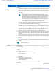
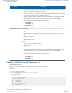


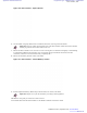


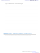
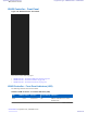
Table Of Contents
- 5827 Exhibit D - User Information
- Tune-Up Procedure
- User Manual
- MANUAL COVER PAGE
- Copyrights
- CMM Labeling and Disclosure Table
- Service Information
- Document History
- Contents
- List of Figures
- List of Tables
- List of Processes
- List of Procedures
- About MTS LiTE, MTS 2 and MTS 4 Installation, Configuration and Basic Service Manual
- MTS Overview
- General Safety
- Radio Frequency Distribution System
- RFDS Theory of Operation
- MTS LiTE and MTS 2 RFDS
- MTS 4 RFDS
- Expansion Cabinet RFDS
- Site Controller
- XHUB Controller
- Base Radio
- Power Supply Unit
- Cooling Fans
- Technical Specifications
- Environmental and Standards Specifications
- Cabinet and Module Specifications
- MTS Cabinets Frequency Range
- Dimensions of the MTS Cabinets
- RF Specifications
- Transmitter Specifications
- Receiver Specifications
- Site Controller Specifications
- Internal GPS Module Input Specifications
- MTS LiTE / MTS 2 Duplexer Specifications
- MTS LiTE / MTS 2 Preselector Specifications
- MTS 4 Duplexer Specifications
- MTS 4 Post Filter Specifications
- MTS 4 Preselector Specifications
- Auto Tune Cavity Combiner (ATCC) Specifications
- Manual Tune Cavity Combiner (MTCC) Specifications
- Hybrid Combiner Specifications
- Base Radio Specifications
- Power Supply Unit Specifications
- XHUB Controller Specifications
- RX Splitter Specifications
- MTS LiTE, MTS 2, and MTS 4 Connectors
- Expansion Options
- MTS 4 Outdoor Enclosure
- Appendix A: Field Replaceable Units (FRUs)
- Appendix B: Planned Maintenance Inspection (PMI)
- Appendix C: Static Precautions and ESD Strap
- Appendix D: TETRA/Dimetra Acronyms

Figure 170: Site Controller - Captive Screws
6 Use the handle, and gently slide the Site Controller from the slot, removing it from the chassis.
Important: There are cables connected at the rear of the Site Controller. Slide out the Site Controller
carefully, tag and disconnect ribbon cables at the rear.
7 Remove the Site Controller cover. Unscrew 19 screws securing the cover and slide it off gently to avoid damage
to components installed on the board (the cover can harm the springs on the RJ45 connectors (front side
connectors), when the cover has been slid nearly completely off).
8 Remove the old battery from the socket on the board.
Figure 171: Site Controller - Lithium Battery Location
9 Install a replacement battery (Motorola p/n 5185151Y02) in its socket on the board.
Important: Dispose or recycle the used battery according to local regulations.
10 Slide the cover gently on and secure it with 19 screws.
11 Install the Site Controller into the MTS. Use the handle to slide the unit into the chassis.
Site Controller | 277
6802800U74-AD | September 2014 | Send Feedback
Applicant: Motorola Solutions
Equipment Type: ABZ89FC5827 / 109AB-5827
Exhibit D2