
User's Manual
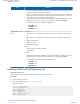


Table Of Contents
- 5827 Exhibit D - User Information
- Tune-Up Procedure
- User Manual
- MANUAL COVER PAGE
- Copyrights
- CMM Labeling and Disclosure Table
- Service Information
- Document History
- Contents
- List of Figures
- List of Tables
- List of Processes
- List of Procedures
- About MTS LiTE, MTS 2 and MTS 4 Installation, Configuration and Basic Service Manual
- MTS Overview
- General Safety
- Radio Frequency Distribution System
- RFDS Theory of Operation
- MTS LiTE and MTS 2 RFDS
- MTS 4 RFDS
- Expansion Cabinet RFDS
- Site Controller
- XHUB Controller
- Base Radio
- Power Supply Unit
- Cooling Fans
- Technical Specifications
- Environmental and Standards Specifications
- Cabinet and Module Specifications
- MTS Cabinets Frequency Range
- Dimensions of the MTS Cabinets
- RF Specifications
- Transmitter Specifications
- Receiver Specifications
- Site Controller Specifications
- Internal GPS Module Input Specifications
- MTS LiTE / MTS 2 Duplexer Specifications
- MTS LiTE / MTS 2 Preselector Specifications
- MTS 4 Duplexer Specifications
- MTS 4 Post Filter Specifications
- MTS 4 Preselector Specifications
- Auto Tune Cavity Combiner (ATCC) Specifications
- Manual Tune Cavity Combiner (MTCC) Specifications
- Hybrid Combiner Specifications
- Base Radio Specifications
- Power Supply Unit Specifications
- XHUB Controller Specifications
- RX Splitter Specifications
- MTS LiTE, MTS 2, and MTS 4 Connectors
- Expansion Options
- MTS 4 Outdoor Enclosure
- Appendix A: Field Replaceable Units (FRUs)
- Appendix B: Planned Maintenance Inspection (PMI)
- Appendix C: Static Precautions and ESD Strap
- Appendix D: TETRA/Dimetra Acronyms

Unit Function
• Cavity tune timeout: establishes a timeout period between a fine-tuning of the cavities.
All cavities must be fine-tuned at the timeout.
• Park a cavity: instructs the ATCC to park the specified cavity. This involves adjusting
the cavity resonance to a frequency outside of the Tx band. If RF power is present, the
cavity parks and then re-tunes to the input frequency.
• VSWR Alarm Threshold: establishes a threshold for enabling a VSWR Alarm. Valid
threshold values are in the range 1.00 to 10.00 where 1.00 means No VSWR.
Recommended values for each MTS configuration are:
- 400 MHz: 3.00
- 260 MHz: 3.00
- 800 MHz: 4.00
DPM (Duplexer, Post
Filter)
Monitoring:
•
Forward power on a digital power monitor: the input power range is from 0 W to 150
W.
• Reverse power on a digital power monitor: the input power range is from 0 W to 40
W.
• VSWR from a DPM.
• DPM temperature.
• DPM Heartbeat signal.
Alarms:
• SW is corrupted or unable to initialize.
• VSWR alarm.
Controls:
• VSWR Alarm Threshold: establishes a threshold for enabling a VSWR Alarm. Valid
threshold values are in the range 1.00 to 10.00 where 1.00 means No VSWR.
Recommended values for each MTS configuration are:
- 400 MHz: 3.00
- 260 MHz: 3.00
- 800 MHz: 4.00
Updating CAN Bus TrackID Mapping List
When and where to use:
Perform this procedure to update the Mapping List with the New Unit TrackID.
Procedure:
1 Log on to the Site Controller.
2 To view the mapping list, type can check_mapping.
See example below:
SC> can check_mapping
Units are present:
Device Track ID
DPM 1 JTH0500101
PSU 1 JTH0500200
Units are not present:
DPM 2 JTH0500105
274 | Site Controller
Send Feedback | September 2014 | 6802800U74-AD
Applicant: Motorola Solutions
Equipment Type: ABZ89FC5827 / 109AB-5827
Exhibit D2