
User's Manual


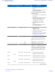
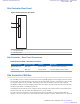

Table Of Contents
- 5827 Exhibit D - User Information
- Tune-Up Procedure
- User Manual
- MANUAL COVER PAGE
- Copyrights
- CMM Labeling and Disclosure Table
- Service Information
- Document History
- Contents
- List of Figures
- List of Tables
- List of Processes
- List of Procedures
- About MTS LiTE, MTS 2 and MTS 4 Installation, Configuration and Basic Service Manual
- MTS Overview
- General Safety
- Radio Frequency Distribution System
- RFDS Theory of Operation
- MTS LiTE and MTS 2 RFDS
- MTS 4 RFDS
- Expansion Cabinet RFDS
- Site Controller
- XHUB Controller
- Base Radio
- Power Supply Unit
- Cooling Fans
- Technical Specifications
- Environmental and Standards Specifications
- Cabinet and Module Specifications
- MTS Cabinets Frequency Range
- Dimensions of the MTS Cabinets
- RF Specifications
- Transmitter Specifications
- Receiver Specifications
- Site Controller Specifications
- Internal GPS Module Input Specifications
- MTS LiTE / MTS 2 Duplexer Specifications
- MTS LiTE / MTS 2 Preselector Specifications
- MTS 4 Duplexer Specifications
- MTS 4 Post Filter Specifications
- MTS 4 Preselector Specifications
- Auto Tune Cavity Combiner (ATCC) Specifications
- Manual Tune Cavity Combiner (MTCC) Specifications
- Hybrid Combiner Specifications
- Base Radio Specifications
- Power Supply Unit Specifications
- XHUB Controller Specifications
- RX Splitter Specifications
- MTS LiTE, MTS 2, and MTS 4 Connectors
- Expansion Options
- MTS 4 Outdoor Enclosure
- Appendix A: Field Replaceable Units (FRUs)
- Appendix B: Planned Maintenance Inspection (PMI)
- Appendix C: Static Precautions and ESD Strap
- Appendix D: TETRA/Dimetra Acronyms

replace the track number of the defective FRU with the new track number in the mapping list, that way the new track
number is mapped to the function of the replaced FRU.
Figure 169: Site Controller - CAN Bus
Table 80: Site Controller - CAN Bus Functionality
Unit Function
PSU Monitoring:
• PSU temperature: -30 °C to +100 °C, tolerance: 2 °C.
• Battery current: -20 A to +10 A, tolerance: ±1%.
•
Battery voltage: 30 V to 60 V, tolerance: ±1%.
• Battery temperature: -30 °C to +100 °C, tolerance: 2 °C.
• 7 V output voltage: 0 V to 10 V, tolerance: ±2%.
• 7 V output current: 0 A to 10 A, tolerance: ±2%.
• 28.5 V output voltage: 0 V to 30 V, tolerance: ±2%.
• 28.5 V output current: 0 A to 10 A, tolerance: ±2%.
• PSU output power: 0 W to 1100 W, tolerance: ±2%.
• Fan output voltage: 0 V to 30 V, tolerance: ±2%.
• PSU input air temp.: -30 °C to +100 °C, tolerance: ±2 °C.
Alarms:
• DC Source Fail: Indicating DC input voltage outside limits (below 43 V).
• DC Out Fail: DC output voltages out of limits.
• AC Source Fail: Early warning, indicating that the AC input is interrupted and the
PSU starts to operate from DC input source in 15 ms. (if a backup source is present).
• Software Fail: Indicating software is corrupted or unable to initialize.
• Over Temperature: Indicating over temperature detected 5 °C to 10 °C before shut-
down.
• Fan 1 alarm: Fan 1 not operating (fan has stopped or its running speed is below speci-
fication), PSU has received a high signal (open collector) from fan tray 1 through fan
connector 1.
• Fan 2 alarm: Fan 2 not operating (fan has stopped or its running speed is below speci-
fication), PSU has received a high signal (open collector) from fan tray 2 through fan
connector 2.
• Fan 3 alarm: Fan 3 not operating (fan has stopped or its running speed is below speci-
fication), PSU has received a high signal (open collector) from fan tray 3 through fan
connector 3.
Table continued…
272 | Site Controller
Send Feedback | September 2014 | 6802800U74-AD
Applicant: Motorola Solutions
Equipment Type: ABZ89FC5827 / 109AB-5827
Exhibit D2