APPLICANT: MOTOROLA SOLUTIONS EQUIPMENT TYPE: ABZ89FC5827 109AB-5827 User Information User Information Tune-up and user / operational manual information are provided in the following exhibits.
APPLICANT: MOTOROLA SOLUTIONS EQUIPMENT TYPE: ABZ89FC5827 109AB-5827 User Information Tune-Up Procedure Aside from the 3rd party cavity combiners, there is no field tune-up procedure. All adjustments are software controlled and are pre-set at the factory. Certain station operating parameters can be changed via man-machine interface (MMI) commands, within predetermined limits. Examples include transmit / receive operating frequencies and transmitter power level.
APPLICANT: MOTOROLA SOLUTIONS EQUIPMENT TYPE: ABZ89FC5827 109AB-5827 User Information Operational or User’s Manual The manual should include instruction, installation, operator, or technical manuals with required ‘information to the users’. This manual should include a statement that cautions the user that changes or modifications not expressly approved by the party responsible for compliance could void the user’s authority to operate the equipment.
Applicant: Motorola Solutions Equipment Type: ABZ89FC5827 / 109AB-5827 DIMETRA™ Dimetra IP Scalable (DIPS) Dimetra IP Compact (DIPC)/Scalable Dimetra IP (SDIP) Dimetra IP Micro/Dimetra IP LiTE MTS LITE, MTS 2 AND MTS 4 INSTALLATION, CONFIGURATION AND BASIC SERVICE MANUAL September 2014 *6802800U74* 6802800U74-AD © 2014 Motorola Solutions, Inc.
Applicant: Motorola Solutions Equipment Type: ABZ89FC5827 / 109AB-5827 Exhibit D2
Applicant: Motorola Solutions Equipment Type: ABZ89FC5827 / 109AB-5827 3 | Copyrights Copyrights The Motorola products described in this document may include copyrighted Motorola computer programs. Laws in the United States and other countries preserve for Motorola certain exclusive rights for copyrighted computer programs.
Applicant: Motorola Solutions Equipment Type: ABZ89FC5827 / 109AB-5827 Exhibit D2
Applicant: Motorola Solutions Equipment Type: ABZ89FC5827 / 109AB-5827 5 | CMM Labeling and Disclosure Table CMM Labeling and Disclosure Table The People’s Republic of China requires that our products comply with China Management Methods (CMM) environmental regulations. (China Management Methods refers to the Regulation Management Methods for Controlling Pollution by Electronic Information Products.) Two items are used to demonstrate compliance; the Label and the Disclosure Table.
Applicant: Motorola Solutions Equipment Type: ABZ89FC5827 / 109AB-5827 Exhibit D2
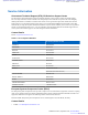
Applicant: Motorola Solutions Equipment Type: ABZ89FC5827 / 109AB-5827 7 | Service Information Service Information Government Technical Support (GTS), EA Solutions Support Centre The Government Technical Support (GTS), EA Solutions Support Centre provides a remote Technical Support Service to help customers resolve technical issues and quickly restore networks and systems.
Applicant: Motorola Solutions 8 | Service Information • • • Equipment Type: ABZ89FC5827 / 109AB-5827 Telephone: +49 (0) 30 66861404 Telefax: +49 (0) 30 66861426 Monday – Friday 08:00 am to 06:00 pm (CET) Parts Identification and Ordering Request for help in identification of non-referenced spare parts should be directed to the Customer Care Organization of Motorola’s local area representation.
Applicant: Motorola Solutions Equipment Type: ABZ89FC5827 / 109AB-5827 9 | Document History Document History Version Description Date 6802800U74–A Initial Edition July 2006 6802800U74–B Minor changes Aug. 2006 6802800U74–C Table 4–4 updated Aug. 2006 Table 4–5 updated and note inserted Table 5–6 updated 6802800U74–D Service Cable and Connector Box Description section updated Oct. 2006 6802800U74–E Updates throughout the manual Feb.
Applicant: Motorola Solutions 10 | Document History Version Equipment Type: ABZ89FC5827 / 109AB-5827 Description • • • • • Date 260 MHz additions throughout the manual. Updated information on LVD Kit Installation Updated MTS 4 Duplexer FB diagram Updated procedure How to configure E1 links other minor updates 6802800U74–R Added non-duplexed MTS 2 configurations Sep. 2010 6802800U74–T Added MTS LiTE Dec.
Applicant: Motorola Solutions Version Equipment Type: ABZ89FC5827 / 109AB-5827 Document History | 11 Description • Date Verifying and Tuning the Receiver RSSI Levels on page 224 Updated: • • 6802800U74–AA Ethernet Site Link on page 328 Site Controller – Front Panel Indicators (LED) on page 267 Feb. 2013 Added: • • Encrypted Ethernet Site Links on page 331 Verifying Encryption Capability on page 332 Updated: • 6802800U74–AB Updated the following: • • • • • • 6802800U74–AC Mar.
Applicant: Motorola Solutions Equipment Type: ABZ89FC5827 / 109AB-5827 Exhibit D2
Applicant: Motorola Solutions Equipment Type: ABZ89FC5827 / 109AB-5827 Contents | 13 Contents Copyrights........................................................................................................................................ 3 CMM Labeling and Disclosure Table............................................................................................5 Service Information.........................................................................................................................
Applicant: Motorola Solutions 14 | Contents Equipment Type: ABZ89FC5827 / 109AB-5827 Site Planning........................................................................................................................................................55 Site Survey.............................................................................................................................................. 55 Site Selection Considerations.......................................................................
Applicant: Motorola Solutions Equipment Type: ABZ89FC5827 / 109AB-5827 Contents | 15 RF Antenna Connections...................................................................................................................................102 Expansion Cabinet Connections........................................................................................................................106 TX Connections.....................................................................................................
Applicant: Motorola Solutions 16 | Contents Equipment Type: ABZ89FC5827 / 109AB-5827 Ethernet Site Link Cabling – MTS 4 with Dual Site Controller........................................................... 157 Ethernet Site Link Cabling – MTS 4 Expansion Cabinet with Single Site Controller......................... 159 Ethernet Site Link Cabling – MTS 4 Expansion Cabinet with Dual Site Controller............................160 RF Cabling.......................................................................
Applicant: Motorola Solutions Equipment Type: ABZ89FC5827 / 109AB-5827 Contents | 17 Corrective Actions for the Base Radio Receiver Configuration............................................... 218 Configuring the pm_config....................................................................................................... 219 Configuring the Base Radio VSWR......................................................................................................220 Station Verification Procedures............
Applicant: Motorola Solutions 18 | Contents Equipment Type: ABZ89FC5827 / 109AB-5827 Site Controller – Lithium Battery......................................................................................................................275 Resetting the RTC Battery Status..........................................................................................................275 Checking if the Site Controller Lithium Battery Needs Changing.......................................................
Applicant: Motorola Solutions Equipment Type: ABZ89FC5827 / 109AB-5827 Contents | 19 Chapter 13: MTS Troubleshooting.................................................................... 311 Site Controller Troubleshooting........................................................................................................................311 Site Controller Fault Indications...........................................................................................................
Applicant: Motorola Solutions 20 | Contents Equipment Type: ABZ89FC5827 / 109AB-5827 Chapter 15: Expansion Options..........................................................................373 Additional Base Radio for MTS 2.....................................................................................................................373 Cable Connections.................................................................................................................................
Applicant: Motorola Solutions Equipment Type: ABZ89FC5827 / 109AB-5827 Contents | 21 Appendix C: Static Precautions and ESD Strap................................................ 419 Static Sensitive Precautions...............................................................................................................................419 ESD Wrist Strap Safety Precautions.................................................................................................................
Applicant: Motorola Solutions 22 | Contents Equipment Type: ABZ89FC5827 / 109AB-5827 Exhibit D2
Applicant: Motorola Solutions Equipment Type: ABZ89FC5827 / 109AB-5827 List of Figures | 23 List of Figures Figure 1: MTS LiTE Cabinet ......................................................................................................................................... 42 Figure 2: MTS 2 Cabinet ................................................................................................................................................44 Figure 3: MTS 4 Cabinet .......................................
Applicant: Motorola Solutions 24 | List of Figures Equipment Type: ABZ89FC5827 / 109AB-5827 Figure 49: MTS LVD Kit Relay Connection Diagram – Dual PSU, Dual Batteries ..................................................... 99 Figure 50: MTS LVD Kit Relay Connection Diagram – Dual PSU, Single Battery ................................................... 100 Figure 51: MTS LVD Kit Battery Cable Connections .................................................................................................
Applicant: Motorola Solutions Equipment Type: ABZ89FC5827 / 109AB-5827 List of Figures | 25 Figure 101: Ethernet Site Link Cabling for MTS 2 ......................................................................................................154 Figure 102: Ethernet Site Link Cabling for MTS 4 with Single Site Controller ..........................................................156 Figure 103: Ethernet Site Link Cabling for MTS 4 with Dual Site Controller .................................................
Applicant: Motorola Solutions 26 | List of Figures Equipment Type: ABZ89FC5827 / 109AB-5827 Figure 148: MTS 4 TX on one Antenna and up to three RX Antennas Filter Configuration ......................................244 Figure 149: MTS 4 TX on one Antenna and two RX Antennas Filter Configuration ................................................. 244 Figure 150: MTS 4 TX on one Antenna and three RX Antennas Filter Configuration ...............................................
Applicant: Motorola Solutions Equipment Type: ABZ89FC5827 / 109AB-5827 List of Figures | 27 Figure 199: RF Cabling Diagram of MTS 4 with two TX ant. After Expansion .........................................................386 Figure 200: E1 and Ethernet Cabling of MTS 4 After Expansion ............................................................................... 387 Figure 201: ATCC Cabling Diagram — MTS 4 with 1 TX Antenna before Expansion .............................................
Applicant: Motorola Solutions 28 | List of Figures Equipment Type: ABZ89FC5827 / 109AB-5827 Exhibit D2
Applicant: Motorola Solutions Equipment Type: ABZ89FC5827 / 109AB-5827 List of Tables | 29 List of Tables Table 1: List of Telephone Numbers ................................................................................................................................7 Table 2: Preselector Filter Bandwidth ............................................................................................................................48 Table 3: Duplexer Filter Bandwidth .......................................
Applicant: Motorola Solutions 30 | List of Tables Equipment Type: ABZ89FC5827 / 109AB-5827 Table 49: TX ATCC Interconnect Harness Part Numbers ...........................................................................................172 Table 50: RF Cabling for MTS 4 with One TX/RX Antenna and Up to Two Additional RX Antennas .................... 174 Table 51: RF Cabling/Connections for MTS 4 with Two TX/RX ant. and Up to One Additional RX ant. ................
Applicant: Motorola Solutions Equipment Type: ABZ89FC5827 / 109AB-5827 List of Tables | 31 Table 99: Recommended Test Equipment ................................................................................................................... 351 Table 100: Base Radio Fault Indications ..................................................................................................................... 354 Table 101: Miscellaneous Troubleshooting Items .....................................................
Applicant: Motorola Solutions 32 | List of Tables Equipment Type: ABZ89FC5827 / 109AB-5827 Exhibit D2
Applicant: Motorola Solutions Equipment Type: ABZ89FC5827 / 109AB-5827 33 | List of Processes List of Processes Installation Prerequisites ................................................................................................................................................ 76 Installing the Cabinet Using the Mounting Plate ........................................................................................................... 82 Performing a Final Check-Out after Installation ................
Applicant: Motorola Solutions Equipment Type: ABZ89FC5827 / 109AB-5827 Exhibit D2
Applicant: Motorola Solutions Equipment Type: ABZ89FC5827 / 109AB-5827 35 | List of Procedures List of Procedures Receiving the MTS Equipment ...................................................................................................................................... 75 Moving the MTS 4 and Expansion Cabinet ................................................................................................................... 77 Installing the Cabinet Using the Mounting Brackets .....................
Applicant: Motorola Solutions 36 | List of Procedures Equipment Type: ABZ89FC5827 / 109AB-5827 Reinstalling the Hybrid Combiner ............................................................................................................................... 242 Removing the MTS 4 Preselector ................................................................................................................................ 246 Reinstalling the MTS 4 Preselector ...................................................
Applicant: Motorola Solutions Equipment Type: ABZ89FC5827 / 109AB-5827 37 | About MTS LiTE, MTS 2 and MTS 4 Installation, Configuration and Basic Service Manual About MTS LiTE, MTS 2 and MTS 4 Installation, Configuration and Basic Service Manual This manual provides an overview of the Motorola TETRA Station (MTS) within the Dimetra IP System.
Applicant: Motorola Solutions Equipment Type: ABZ89FC5827 / 109AB-5827 38 | About MTS LiTE, MTS 2 and MTS 4 Installation, Configuration and Basic Service Manual Document Title Description tions.
Applicant: Motorola Solutions Equipment Type: ABZ89FC5827 / 109AB-5827 About MTS LiTE, MTS 2 and MTS 4 Installation, Configuration and Basic Service Manual | 39 Style Conventions The following style conventions are used: Convention Description Bold This typeface is used for names of, for instance, windows, buttons, and labels when these names appear on the screen (example: the Alarms Browser window).
Applicant: Motorola Solutions Equipment Type: ABZ89FC5827 / 109AB-5827 40 | About MTS LiTE, MTS 2 and MTS 4 Installation, Configuration and Basic Service Manual Note: This is a Class A product. In a domestic environment, this product may cause radio interference in which case you may be required to take adequate measures. Article 3.
Applicant: Motorola Solutions Equipment Type: ABZ89FC5827 / 109AB-5827 41 | MTS Overview Chapter 1 MTS Overview Motorola TETRA Station (MTS) is a Base Station of a Dimetra IP communication system. A Base Station serves as the Radio Frequency (RF) interface between the system infrastructure and the mobile stations.
Applicant: Motorola Solutions 42 | MTS Overview Equipment Type: ABZ89FC5827 / 109AB-5827 The three versions of MTS are, in general, similar in terms of functionality and the modules that they are comprised of. However, there are a number of important differences between them, which are highlighted in appropriate sections of this document. The system infrastructures Network Management (NM) applications mange the MTSs. Communication between the MTSs and the NM applications takes place through E1 , X.
Applicant: Motorola Solutions • Equipment Type: ABZ89FC5827 / 109AB-5827 MTS Overview | 43 Power Supply Unit The door of the cabinet has a lock to prevent unauthorized opening. Unauthorized opening of the door generates an alarm. For a complete description of each module, refer to the appropriate chapter. Each chapter provides the theory of operation, a description of switches, indicators and connectors, and FRU replacement procedures for each module.
Applicant: Motorola Solutions 44 | MTS Overview Equipment Type: ABZ89FC5827 / 109AB-5827 Figure 2: MTS 2 Cabinet The modules that comprise the MTS 2 cabinet vary based on the type of configuration chosen. A typical configuration includes the following modules: • • • • • • Duplexer Preselector Hybrid Combiner Site Controller Base Radio(s) Power Supply Unit The door of the cabinet has a lock to prevent unauthorized opening. Unauthorized opening of the door generates an alarm.
Applicant: Motorola Solutions Equipment Type: ABZ89FC5827 / 109AB-5827 MTS Overview | 45 MTS 4 Components The MTS 4 consists of the following components: • • • • • • • • • Stainless steel and painted aluminum cabinet Removable front door opening to left or right A junction panel Filter section Combiner section One or two 19-inch card cages Interface cabling Internal modules Cooling fans MTS 4 cabinet is available in 260 MHz, 400 MHz, and 800 MHz versions.
Applicant: Motorola Solutions 46 | MTS Overview • • • • Equipment Type: ABZ89FC5827 / 109AB-5827 Cavity Combiner Site Controller Base Radios Power Supply Unit The cabinet door has a lock that prevents non-permitted access and that generates an alarm if unauthorized door opening occurs.
Applicant: Motorola Solutions Equipment Type: ABZ89FC5827 / 109AB-5827 MTS Overview | 47 The modules that comprise the Expansion Cabinet vary based on the type of configuration chosen. A typical configuration includes the following modules: • • • • • RX Splitter(s) Cavity Combiner(s) eXpansion HUB (XHUB) Base Radios Power Supply Unit(s) The door of the cabinet has a lock to prevent unauthorized opening. Unauthorized opening of the door generates an alarm.
Applicant: Motorola Solutions 48 | MTS Overview Equipment Type: ABZ89FC5827 / 109AB-5827 Table 2: Preselector Filter Bandwidth MTS Frequency Bandwidth Description 260 MHz 6 MHz Designed to block transmitter frequencies as close as 6 MHz from its band edges. 400 MHz 5 MHz Designed to block transmitter frequencies as close as 5 MHz from its band edges. 800 MHz 19 MHz Designed to block transmitter frequencies as close as 19 MHz from its band edges.
Applicant: Motorola Solutions Equipment Type: ABZ89FC5827 / 109AB-5827 MTS Overview | 49 The following Cavity Combiner (CC) are available: • • Auto Tune Cavity Combiners (ATCC) Manual Tune Cavity Combiners (MTCC) MTCCs are functionally the same as ATCCs except that they are tuned manually instead of electronically. Note: 260 MHz configurations do not support MTCC. MTS LiTE and MTS 2 do not support Cavity Combiners.
Applicant: Motorola Solutions 50 | MTS Overview Equipment Type: ABZ89FC5827 / 109AB-5827 Base Radio Module The Base Radio (BR) provides reliable digital communication capabilities. Each Base Radio contains the following subcomponents: • • Transceiver Power Amplifier (PA) Base Radio Transceiver The transceiver provides the BRs with signal transmission, receiving, processing, and modulation functions, incorporating a Base Radio Controller (BRC), Receiver (RCV), and Exciter (EXC).
Applicant: Motorola Solutions Equipment Type: ABZ89FC5827 / 109AB-5827 51 | General Safety Chapter 2 General Safety This chapter summarizes the safety-related information that you should both understand and observe when working with Motorola TETRA Stations (MTSs). In addition to the information contained in this chapter, additional safetyrelated information can be found in other parts of the document. Important: This is not an exhaustive list of all the precautions and safety measures.
Applicant: Motorola Solutions 52 | General Safety Equipment Type: ABZ89FC5827 / 109AB-5827 Caution: To prevent damage of the MTS modules by static discharge, always wear the ESD strap when servicing the MTS equipment. Caution: Ground all antennae cables at the point that they enter the building. Caution: Antenna design is the customers responsibility. All aspects of antenna design must comply with the relevant local regulations.
Applicant: Motorola Solutions Equipment Type: ABZ89FC5827 / 109AB-5827 General Safety | 53 Caution: Harmful gases may be generated by the battery backup. Battery backup should only be operated in well ventilated areas. Warning: Batteries used for powering equipment pose the following risks: • • • Explosion hazard resulting from inherent generation of hydrogen sulfide gas. Chemical burns/blindness resulting from sulfuric acid electrolyte.
Applicant: Motorola Solutions Equipment Type: ABZ89FC5827 / 109AB-5827 229 | Radio Frequency Distribution System Chapter 7 Radio Frequency Distribution System The Radio Frequency Distribution System (RFDS) distributes and manages the communications network frequencies and mitigates interference between multiple radios, allowing them to operate simultaneously. This results in improved radio reception performance across the frequency ranges where multiple transmitters are broadcasting.
Applicant: Motorola Solutions 230 | Radio Frequency Distribution System Equipment Type: ABZ89FC5827 / 109AB-5827 CAN Bus The intercommunication between the RFDS units (the Duplexers, Post Filters, and Cavity Combiners) and the Site Controller is carried out through the CAN Bus at 125 kB/second. The connectors for the CAN Bus are RJ45 connectors. The CAN Bus is terminated at each end, either by the Site Controller or by an RJ45 terminator.
Applicant: Motorola Solutions Equipment Type: ABZ89FC5827 / 109AB-5827 Radio Frequency Distribution System | 231 Note: MTS LiTE supports one Duplexer. Because the MTS 2 has only up to two carriers, there is no need for Post Filters for non-duplexed operation (you can achieve non-duplexed operation by using the Duplexer as the Post Filter and not using the receive path of the Duplexer). • Hybrid Combiner.
Applicant: Motorola Solutions 232 | Radio Frequency Distribution System Equipment Type: ABZ89FC5827 / 109AB-5827 Figure 135: MTS LiTE TX/RX on 1 ant. - Filter Configuration Figure 136: MTS LiTE TX/RX on 1 ant., RX on 1 ant - Filter Configuration Table 72: MTS 2 RF Configurations on page 232 lists all filters configurations for MTS 2 and Figure 137: MTS 2 TX/RX on 2 ant. - Filter Configuration on page 233 to Figure 140: MTS 2 TX/RX on 1 ant.
Applicant: Motorola Solutions Equipment Type: ABZ89FC5827 / 109AB-5827 Radio Frequency Distribution System | 233 Max Power [W] Low Pwr High Pwr Hybrid Combiner TX/RX on 1 ant., RX on 1 ant. 10 25 (10) 1 1 1 TX/RX on 1 ant., RX on 2 ant. 10 25 (10) 1 1 2 RF Configuration Duplexer Preselector Figure 137: MTS 2 TX/RX on 2 ant. - Filter Configuration Figure 138: MTS 2 TX/RX on 2 ant.
Applicant: Motorola Solutions 234 | Radio Frequency Distribution System Equipment Type: ABZ89FC5827 / 109AB-5827 Figure 139: MTS 2 TX/RX on 1 ant., RX on 1 ant - Filter Configuration Figure 140: MTS 2 TX/RX on 1 ant., RX on 2 ant - Filter Configuration MTS LiTE / MTS 2 Preselector The MTS LiTE/MTS 2 Preselector is a bandpass filter, which only allows the receiver signals to pass.
Applicant: Motorola Solutions Equipment Type: ABZ89FC5827 / 109AB-5827 Radio Frequency Distribution System | 235 Figure 141: MTS LiTE / MTS 2 Preselector Note: Unused RX outputs should be terminated. The MTS LiTE/MTS 2 Preselector only has two RX outputs and no expansion output. In MTS LiTE/MTS 2 the Preselector has an integrated high performance low noise amplifier (LNA). The supply voltage for the LNA is supplied through the RX out connected to the Base Radios.
Applicant: Motorola Solutions 236 | Radio Frequency Distribution System Equipment Type: ABZ89FC5827 / 109AB-5827 Figure 142: Schematic Diagram of MTS LiTE / MTS 2 Preselector Note: Unused RX outputs should be terminated. Replacing the MTS LiTE / MTS 2 Preselector For a list of available FRUs, see Field Replaceable Units (FRUs) on page 405. Prerequisites: Warning: RF energy burn hazard. Disconnect power in the cabinet to prevent injury and equipment damage while disconnecting and connecting antennas.
Applicant: Motorola Solutions Equipment Type: ABZ89FC5827 / 109AB-5827 Radio Frequency Distribution System | 237 8 Remove and keep the bracket at the front. Removing the Preselector – MTS 2 Procedure: 1 2 3 4 Remove the door of the cabinet completely. Unscrew the antenna cable. Remove all RX cables connected to the Preselector. Remove the fastening screw behind the antenna. Loosen the two fastening screws at the front enough to free the center tab.
Applicant: Motorola Solutions 238 | Radio Frequency Distribution System Equipment Type: ABZ89FC5827 / 109AB-5827 Figure 143: MTS 2 Duplexer Note: Unused RX outputs should be terminated. The duplex spacing between a transmit frequency and the corresponding receive frequency is 10 MHz, with the transmit frequency highest. This leaves a 5 MHz spacing between the lowest possible transmit frequency and the highest possible receive frequency.
Applicant: Motorola Solutions Equipment Type: ABZ89FC5827 / 109AB-5827 Radio Frequency Distribution System | 239 Figure 144: Schematic Diagram of MTS LiTE / MTS 2 Duplexer Note: Unused RX outputs should be terminated. Replacing the MTS LiTE / MTS 2 Duplexer For a list of available FRUs, see Field Replaceable Units (FRUs) on page 405. Process: 1 Remove the Duplexer, see Removing the MTS LiTE / MTS 2 Duplexer on page 239.
Applicant: Motorola Solutions 240 | Radio Frequency Distribution System Equipment Type: ABZ89FC5827 / 109AB-5827 Reinstalling the MTS LiTE / MTS 2 Duplexer Procedure: 1 Insert the Duplexer into the filter tray. See Inserting the MTS LiTE / MTS 2 Duplexer into the Filter Tray on page 240. 2 Update the mapping list with the new unit TrackID. See Updating the Mapping List with the New Unit TrackID on page 240.
Applicant: Motorola Solutions Equipment Type: ABZ89FC5827 / 109AB-5827 Radio Frequency Distribution System | 241 Hybrid Combiner The Hybrid Combiner is a part of the transmitter path in the RF Distribution System. The Hybrid Combiner provides very reliable combining of up to two transmitters. The Hybrid Combiner has no limitations in respect to channel spacing of the TX channels; however, for frequency planning and interference reasons, at least 50 kHz is recommended.
Applicant: Motorola Solutions 242 | Radio Frequency Distribution System 2 Equipment Type: ABZ89FC5827 / 109AB-5827 Warning: The Hybrid Combiner may be hot. To avoid injury, allow the Hybrid Combiner to cool down before servicing. 3 Remove the TX and antenna cables. 4 Loosen the two screws that secure the Hybrid Combiner onto the bracket. 5 Slide the Hybrid Combiner forward and pull free from the screws. Slide it out from the bracket.
Applicant: Motorola Solutions Equipment Type: ABZ89FC5827 / 109AB-5827 Radio Frequency Distribution System | 243 Table 73: MTS 4 RF Configurations Max Power [W] Cavity Combiner Duplexer Pre selector Post Filter 40 (20) - 2 - - 25 40 (20) - 2 1 - TX on 2 ant., RX on 2 ant. 25 40 (20) - - 2 2 TX on 2 ant., RX on 3 ant. 25 40 (20) - - 3 2 TX/RX on 1 ant., RX on 1 ant. 10 25 (10) 1 1 1 - TX/RX on 1 ant., RX on 2 ant. 10 25 (10) 1 1 2 - TX on 1 ant., RX on 2 ant.
Applicant: Motorola Solutions 244 | Radio Frequency Distribution System Equipment Type: ABZ89FC5827 / 109AB-5827 Figure 147: MTS 4 TX/RX on two Antennas and up to one RX Antenna Filter Configuration PRESELECTOR DUPLEXER CAN IN DUPLEXER CAN OUT CAN IN CAN OUT Figure 148: MTS 4 TX on one Antenna and up to three RX Antennas Filter Configuration PRESELECTOR PRESELECTOR PRESELECTOR POSTFILTER CAN IN CAN OUT Figure 149: MTS 4 TX on one Antenna and two RX Antennas Filter Configuration PRESELECTOR PR
Applicant: Motorola Solutions Equipment Type: ABZ89FC5827 / 109AB-5827 Radio Frequency Distribution System | 245 The filter’s bandwidth is designed to block transmitter frequencies. The receive and transmit bandpass are 10 MHz apart for 400 MHz, 9 MHz apart for 260 MHz, and 45 MHz apart for 800 MHz. The Preselector incorporates an LNA followed by an RMC. The MTS 4 Preselector has four RX outputs and one expansion output.
Applicant: Motorola Solutions 246 | Radio Frequency Distribution System Equipment Type: ABZ89FC5827 / 109AB-5827 Figure 152: Schematic Diagram of MTS 4 Preselector Replacing the MTS 4 Preselector Warning: RF energy burn hazard. Disconnect power in the cabinet to prevent injury and equipment damage while disconnecting and connecting antennas. Process: 1 Remove the Preselector. See Removing the MTS 4 Preselector on page 246. 2 Reinstall the Preselector. See Reinstalling the MTS 4 Preselector on page 247.
Applicant: Motorola Solutions Equipment Type: ABZ89FC5827 / 109AB-5827 Radio Frequency Distribution System | 247 Reinstalling the MTS 4 Preselector Procedure: 1 2 3 4 5 6 7 Fasten the Preselector onto the bracket. Slide the Preselector into the cabinet. Tighten the two fastening screws at the front. Screw on the antenna cable and connect the RX cables to the back of the Preselector. Slide on the top rear and front panels and fasten these with screws. Put the front panel back on and screw this into place.
Applicant: Motorola Solutions 248 | Radio Frequency Distribution System Equipment Type: ABZ89FC5827 / 109AB-5827 Figure 153: MTS 4 Duplexer Figure 154: Schematic Diagram of MTS 4 Duplexer Send Feedback | September 2014 | 6802800U74-AD Exhibit D2
Applicant: Motorola Solutions Equipment Type: ABZ89FC5827 / 109AB-5827 Radio Frequency Distribution System | 249 Replacing the MTS 4 Duplexer Process: 1 Remove the Duplexer. See Removing the MTS 4 Duplexer on page 249. 2 Insert the Duplexer into the filter tray. See Inserting the MTS 4 Duplexer into the Cabinet on page 249. 3 Update the mapping list with the new unit TrackID. See Updating the Mapping List with the New Unit TrackID on page 249.
Applicant: Motorola Solutions 250 | Radio Frequency Distribution System Equipment Type: ABZ89FC5827 / 109AB-5827 2 View the mapping list by entering: can check_mapping. Step example: Units are present: Device Track ID DPM 1 JTH0500101 PSU 1 JTH0500200 Units are not present: DPM 2 JTH0500105 Track ID not mapped: JTH0500102 3 On the mapping list, locate the removed unit indicated as Units are not present. 4 Delete the old CAN Bus unit from the CAN Bus unit mapping list by entering: can remove_mapping .
Applicant: Motorola Solutions Equipment Type: ABZ89FC5827 / 109AB-5827 Radio Frequency Distribution System | 251 Figure 155: Post Filter Figure 156: Schematic Diagram of Post Filter Replacing the Post Filter For a list of available FRUs, see Field Replaceable Units (FRUs) on page 405. Process: 1 Remove the Post Filter, see Removing the Post Filter on page 252. 2 Install the Post Filter into the cabinet, see Inserting the Post Filter into the Cabinet on page 252.
Applicant: Motorola Solutions 252 | Radio Frequency Distribution System Equipment Type: ABZ89FC5827 / 109AB-5827 Removing the Post Filter Procedure: Warning: RF energy hazard and potential equipment damage precaution. 1 2 3 4 5 6 To prevent accidental contact with high energy and injury to personnel, switch off the Power Supply Unit. Remove the four screws holding the front panel. Loosen the two screws holding the front section of the top panel and slide off the panel.
Applicant: Motorola Solutions Equipment Type: ABZ89FC5827 / 109AB-5827 Radio Frequency Distribution System | 253 3 On the mapping list, locate the removed unit indicated as Units are not present. 4 Delete the old CAN Bus unit from the CAN Bus unit mapping list by entering: can remove_mapping . identifies the old unit name and is digit between 0 and 3. Step example: can remove_mapping dpm 2. 5 Add the new CAN Bus unit to the CAN Bus unit mapping list by entering: add_mapping dpm
Applicant: Motorola Solutions 254 | Radio Frequency Distribution System Equipment Type: ABZ89FC5827 / 109AB-5827 Cavity Combiner - Theory of Operation A minimum of 2 watts is needed at a cavity input. The ATCC will automatically tune in 40 seconds maximum. For more detail, see the ATCC specification.
Applicant: Motorola Solutions 2 3 4 5 Equipment Type: ABZ89FC5827 / 109AB-5827 Radio Frequency Distribution System | 255 To prevent accidental contact with high energy and injury to personnel, switch off the Power Supply Unit. Remove the door of the cabinet completely. Remove the three screws fastening the Cavity Combiner to the brackets of the cabinet. Two screws are on the left and one is on the right side of the Cavity Combiner. Remove all TX and signal cables.
Applicant: Motorola Solutions 256 | Radio Frequency Distribution System Equipment Type: ABZ89FC5827 / 109AB-5827 Updating the Mapping List with the New TrackID Procedure: 1 Log on to the Site Controller. 2 View the mapping list by entering: can check_mapping.
Applicant: Motorola Solutions Equipment Type: ABZ89FC5827 / 109AB-5827 Radio Frequency Distribution System | 257 3 Loosen the all the locking knobs of the MTCC, see figure below (the design of the MTCC may look slightly different), and turn the tuning knobs counter clock wise as many turns as possible. 4 Power up the BTS and let all BRs key up. Observe that the TX LEDs of all BRs shine. 5 Connect the service computer to the service port of Base Radio 1 and log on.
Applicant: Motorola Solutions 258 | Radio Frequency Distribution System Equipment Type: ABZ89FC5827 / 109AB-5827 Table 74: MTS 4 Expansion Cabinet RF Configurations Max Power (W) Low Pwr High Pwr Cavity Combiner 10 25 1 2 TX/RX on 2 ant., RX 10 on 1 ant. 25 1 3 TX on 2 ant., RX on 2 10 ant. 25 1 2 TX on 2 ant., RX on 3 10 ant. 25 1 3 TX/RX on 1 ant., RX 8 on 1 ant 20 1 + phasing harness 2 TX/RX on 1 ant., RX 8 on 2 ant. 20 1 + phasing harness 3 TX on 1 ant., RX on 2 10 ant.
Applicant: Motorola Solutions Equipment Type: ABZ89FC5827 / 109AB-5827 Radio Frequency Distribution System | 259 Figure 158: Expansion Cabinet with Single Diversity Figure 159: Expansion Cabinet with Dual Diversity 6802800U74-AD | September 2014 | Send Feedback Exhibit D2
Applicant: Motorola Solutions 260 | Radio Frequency Distribution System Equipment Type: ABZ89FC5827 / 109AB-5827 Figure 160: Expansion Cabinet with Triple Diversity RX Splitter The RX Splitter is a passive device functioning as an extension for the Receiver Multi Coupler function of the Duplexer/Preselector in MTS 4 to support eight Base Radios. It is connected to the Exp Cabinet connector on the Duplexer/Preselector present in the MTS 4 Prime Cabinet giving the right signal level for the RX-Splitter.
Applicant: Motorola Solutions Equipment Type: ABZ89FC5827 / 109AB-5827 Radio Frequency Distribution System | 261 Figure 162: Schematic Diagram of RX Splitter Replacing the Expansion Cabinet RX Splitter This process outlines the recommended tasks to be performed to replace the Expansion Cabinet RX Splitter. For a list of available FRUs, see Field Replaceable Units (FRUs) on page 405. Process: 1 Remove the RX splitter, see Removing the RX Splitter on page 261.
Applicant: Motorola Solutions 262 | Radio Frequency Distribution System Equipment Type: ABZ89FC5827 / 109AB-5827 6 Place the front panel back on and screw this into place. 7 Put the door of the cabinet back on. Cavity Combiner See Cavity Combiner on page 253.
Applicant: Motorola Solutions Equipment Type: ABZ89FC5827 / 109AB-5827 263 | Site Controller Chapter 8 Site Controller The following figures show the front and the rear view of the site controller.
Applicant: Motorola Solutions 264 | Site Controller Equipment Type: ABZ89FC5827 / 109AB-5827 Figure 164: Site Controller Rear View Site Controller – Theory of Operation The Site Controller controls resources within the MTS, including assignment of frequencies and slots to mobile stations. The Site Controller incorporates a Global Positioning System (GPS) module. The GPS module provides a high precision timing signal used as reference for the Base Radio receive and transmit functionality.
Applicant: Motorola Solutions Equipment Type: ABZ89FC5827 / 109AB-5827 Site Controller | 265 Figure 165: Site Controller - Functional Block Diagram Site Controller – Indicators, Switches, and Connectors This section contains information on indicators, switches, and connectors of the Site Controller.
Applicant: Motorola Solutions 266 | Site Controller Equipment Type: ABZ89FC5827 / 109AB-5827 Site Controller – Front Panel Figure 166: Site Controller - Front Panel Send Feedback | September 2014 | 6802800U74-AD Exhibit D2
Applicant: Motorola Solutions Equipment Type: ABZ89FC5827 / 109AB-5827 Site Controller | 267 Site Controller – Front Panel Indicators (LED) Figure 167: Site Controller - Front Panel LEDs Position LED10 LED9 BR1 BR3 BR2 BR4 CAN E1 LED6 LED5 LED12 LED11 LED8 LED7 LED16 LED15 Not used LED18 LED17 Service Exp. Cab.
Applicant: Motorola Solutions 268 | Site Controller LED Equipment Type: ABZ89FC5827 / 109AB-5827 LED/Port Name Position Controlled by Indication • • RED Blinking: Calibration is required. GREEN/RED Blinking: Frequency lock is required, pull in. Forced Non-Synchronized Configuration (FNC) Mode: • • • • • • LED4 BTS Alarm Front Panel SW • • • • LED5 LED6 BR1 LED7 OFF: No alarms. GREEN: Not used.
Applicant: Motorola Solutions LED Equipment Type: ABZ89FC5827 / 109AB-5827 Site Controller | 269 LED/Port Name LED9 BR3 LED10 LED11 BR4 LED12 LED13 Service LED14 CAN LED15 Position Controlled by Indication • YELLOW: Ethernet activity present. Port 3 LED1 HW, Enet switch • • OFF: Ethernet link not present. GREEN: Ethernet link present. Port 3 LED2 HW, Enet switch • • OFF: Ethernet activity not present. YELLOW: Ethernet activity present.
Applicant: Motorola Solutions 270 | Site Controller Switch Name Equipment Type: ABZ89FC5827 / 109AB-5827 Switch Function • Push and hold (>3 seconds) for Hard Reset. Site Controller – Front Panel Connectors Table 77: Site Controller - Front Panel Connectors Connector Name Connector Type To/From Comment POWER SUPPLY MOLEX (2 Pin) PSU 28.
Applicant: Motorola Solutions Equipment Type: ABZ89FC5827 / 109AB-5827 Site Controller | 271 Site Controller Rear Panel Figure 168: Site Controller Rear Panel 1 2 1 — X21/Remote GPS 2 — Alarms/Control Site Controller – Rear Panel Connectors Table 79: Site Controller - Rear Panel Connectors Connector Name Connector Type To/From Comment Remote GPS/ X.21 IDE 26pin Junction Panel Connects to remote GPS/ X.
Applicant: Motorola Solutions 272 | Site Controller Equipment Type: ABZ89FC5827 / 109AB-5827 replace the track number of the defective FRU with the new track number in the mapping list, that way the new track number is mapped to the function of the replaced FRU. Figure 169: Site Controller - CAN Bus Table 80: Site Controller - CAN Bus Functionality Unit PSU Function Monitoring: • • • • • • • • • • • PSU temperature: -30 °C to +100 °C, tolerance: 2 °C. Battery current: -20 A to +10 A, tolerance: ±1%.
Applicant: Motorola Solutions Equipment Type: ABZ89FC5827 / 109AB-5827 Site Controller | 273 Unit Function Controls: • FORCE DC: Controls the PSU to force the usage of the DC input if usable, disregard presence of AC. If DC is outside the usable range for the PSU, the PSU shall indicate an alarm using the DC-fail output. If DC input voltage comes below 43 V ±2% and if AC is usable the PSU shall take the input power from AC, disregarding a Force-DC control input.
Applicant: Motorola Solutions 274 | Site Controller Equipment Type: ABZ89FC5827 / 109AB-5827 Unit Function • • • Cavity tune timeout: establishes a timeout period between a fine-tuning of the cavities. All cavities must be fine-tuned at the timeout. Park a cavity: instructs the ATCC to park the specified cavity. This involves adjusting the cavity resonance to a frequency outside of the Tx band. If RF power is present, the cavity parks and then re-tunes to the input frequency.
Applicant: Motorola Solutions Equipment Type: ABZ89FC5827 / 109AB-5827 Site Controller | 275 Track ID not mapped: JTH0500102 3 On the list, locate the unit that you have removed and that is indicated as Units are not present. 4 Delete old CAN Bus unit from the CAN Bus unit mapping list. Type can remove_mapping , where is the old unit name. See example below: SC> can remove_mapping dpm 2 5 Add new CAN Bus unit to the CAN Bus unit mapping list.
Applicant: Motorola Solutions 276 | Site Controller Equipment Type: ABZ89FC5827 / 109AB-5827 Checking if the Site Controller Lithium Battery Needs Changing Procedure: 1 Perform Resetting the RTC Battery Status on page 275. 2 Power down and then Power up the MTS. 3 Use the Site Controller Test Application to check the RTC alarm by typing alarms -ofault_hndlr and press Enter. 4 • If the battery is OK there should be no RTC related alarms reported.
Applicant: Motorola Solutions Equipment Type: ABZ89FC5827 / 109AB-5827 Site Controller | 277 Figure 170: Site Controller - Captive Screws 6 Use the handle, and gently slide the Site Controller from the slot, removing it from the chassis. Important: There are cables connected at the rear of the Site Controller. Slide out the Site Controller carefully, tag and disconnect ribbon cables at the rear. 7 Remove the Site Controller cover.
Applicant: Motorola Solutions 278 | Site Controller Equipment Type: ABZ89FC5827 / 109AB-5827 Important: Connect the ribbon cables at the rear before sliding the unit into the chassis. 12 Secure the Site Controller in the chassis with the captive screws. 13 Except the power cables, reconnect all other cabling to the unit as tagged during the removal. 14 Power up the Site Controller: a Reconnect the power cables to the MTS Power Supply Units. b Set the power switch to the ON position.
Applicant: Motorola Solutions Equipment Type: ABZ89FC5827 / 109AB-5827 279 | XHUB Controller Chapter 9 XHUB Controller Note: The content of this chapter is only supported in Dimetra IP system releases D6.0 and later.
Applicant: Motorola Solutions 280 | XHUB Controller Equipment Type: ABZ89FC5827 / 109AB-5827 XHUB Controller – Theory of Operation Note: MTS 4 sites equipped with Site Controller Rev A or B may experience service interruption to Base Radio(s) located in the Expansion Cabinet. Prior to Expansion Cabinet installation, Site Controllers of Rev A or B must be sent to factory for FPGA upgrade or replacement. Please see TIB 3592 for more information.
Applicant: Motorola Solutions Equipment Type: ABZ89FC5827 / 109AB-5827 XHUB Controller | 281 Figure 173: XHUB Controller – Functional Block Diagram XHUB Controller – Indicators, Switches, and Connectors This section contains information on indicators, switches, and connectors of the XHUB Controller.
Applicant: Motorola Solutions 282 | XHUB Controller Equipment Type: ABZ89FC5827 / 109AB-5827 XHUB Controller – Front Panel Figure 174: XHUB Controller- Front Panel This section contains following topics: • • • XHUB Controller – Front Panel Indicators (LED) on page 282 XHUB Controller – Front Panel Switches on page 284 XHUB Controller – Front Panel Connectors on page 284 XHUB Controller – Front Panel Indicators (LED) The following table lists the Front Panel LEDs.
Applicant: Motorola Solutions LED Equipment Type: ABZ89FC5827 / 109AB-5827 XHUB Controller | 283 LED/Port Name Position Controlled By Indication OFF: XHUB in Standby or Standalone/Impaired Normal mode LED2 Mode Front Panel HW GREEN: Normal or Impaired Normal Mode OFF: Standalone mode LED3 Link Alarm Front Panel HW GREEN: Impaired Normal or Standalone mode OFF: Normal mode LED4 Alarm Front Panel SW RED: If Alarms (Problem or Failure) in Normal mode or Unknown XHUB state FLASH: Impaired No
Applicant: Motorola Solutions 284 | XHUB Controller LED Equipment Type: ABZ89FC5827 / 109AB-5827 LED/Port Name LED19 Prime Cab Position Controlled By Indication Port 8 LED1 OFF: Ethernet link not present GREEN: Ethernet link present Port 8 LED2 OFF: Ethernet activity not present YELLOW: Ethernet activity present XHUB Controller – Front Panel Switches The following table lists the Front Panel switches of the XHUB Controller and their functions.
Applicant: Motorola Solutions Equipment Type: ABZ89FC5827 / 109AB-5827 XHUB Controller | 285 Replacing the XHUB Controller Warning: See Static Precautions and ESD Strap on page 419 before proceeding with replacement process. Procedure: 1 Disconnect the power cables to the MTS Power Supply Units. 2 3 4 5 Warning: Shock Hazard. The MTS contains dangerous voltages, which can cause electrical shock or damage to equipment. Turn off the MTS and remove the power cabling before servicing this equipment.
Applicant: Motorola Solutions Equipment Type: ABZ89FC5827 / 109AB-5827 Exhibit D2
Applicant: Motorola Solutions Equipment Type: ABZ89FC5827 / 109AB-5827 287 | Base Radio Chapter 10 Base Radio This chapter covers the following topics: • • • • Base Radio – Overview on page 287 Base Radio – Theory of Operation on page 288 Base Radio – Indicators and Connectors on page 291 Replacing the Base Radio on page 293 Base Radio – Overview Figure 175: Base Radio 6802800U74-AD | September 2014 | Send Feedback Exhibit D2
Applicant: Motorola Solutions 288 | Base Radio Equipment Type: ABZ89FC5827 / 109AB-5827 The Base Radio provides reliable digital radio capabilities in a compact software-controlled design. High channel capacity is provided through voice compression techniques and Time Division Multiplexing (TDM). On the Base Radio front panel there are connectors and indicators. The indicators provide a means for monitoring various status and operating conditions of the Base Radio, and also aid in isolating failures.
Applicant: Motorola Solutions Equipment Type: ABZ89FC5827 / 109AB-5827 Base Radio | 289 On the front panel, there is a DC power input, three parallel receiver (RX) inputs, a high power transmitter output signal from the power amplifier, a service port, two interfaces to the Site Controllers, and LED indicators. For more information on the LED indicators, see Table 86: Base Radio – LED Indicators on page 291. The following figure shows an overall block diagram of the Base Radio.
Applicant: Motorola Solutions 290 | Base Radio Equipment Type: ABZ89FC5827 / 109AB-5827 All receivers within a given Base Radio are programmed to the same receive frequency. The signals from each receiver are fed to the BRC where a diversity combining algorithm is performed on the signals. The resultant signal is processed for error correction and then sent to the Site Controller through the Ethernet LAN with the appropriate control information regarding its destination.
Applicant: Motorola Solutions Equipment Type: ABZ89FC5827 / 109AB-5827 Base Radio | 291 For 400 MHz low-power PAs, the frequency band is 380 MHz – 470 MHz. For the 260 MHz band, one low-power PA is available. The frequency band is 260 MHz– 275 MHz. For the 800 MHz band, one high-power PA is available. The frequency band is 806 MHz – 870 MHz. For the 900 MHz band, one high-power PA is available. The frequency band is 932 MHz – 942 MHz.
Applicant: Motorola Solutions 292 | Base Radio # Equipment Type: ABZ89FC5827 / 109AB-5827 LED/Port name Type Controlled by Indication • • AMBER: BR is keyed without service GREEN: BR is keyed • • • OFF: No alarms AMBER: not used RED: not used LED 2 Aux Red/Green SW LED 3 Status Red/Green SW Red LED will BR status: turn on before SW • OFF: Status unknown, power off change any indi• GREEN: BRC main application is cation running • AMBER: Waiting for SWDL this is where the BR will wait if no Si
Applicant: Motorola Solutions Name of Connector Equipment Type: ABZ89FC5827 / 109AB-5827 Base Radio | 293 Type To/From Comment RX2 QMA Preselector/ Duplexer RF RX signal and +7 V dc RX3 QMA Preselector/ Duplexer RF RX signal and +7 V dc Tx QMA Hybrid Combiner/ Cavity RF TX signal Combiner Power MOLEX Power Supply Unit Pin 1 - 3 GND Pin 4 +7 V Pin 6 - 7 +28.
Applicant: Motorola Solutions 294 | Base Radio • • • Equipment Type: ABZ89FC5827 / 109AB-5827 Wear a wrist strap (Motorola Part No. 4280385A59 or equivalent) at all times when servicing the Base Radio to minimize static build up. A jack is provided at top left of module cage marked with the ground symbol. Keep spare modules in factory packaging for transporting. When shipping modules, always pack in original packaging. For more information, see Static Precautions and ESD Strap on page 419.
Applicant: Motorola Solutions Equipment Type: ABZ89FC5827 / 109AB-5827 295 | Power Supply Unit Chapter 11 Power Supply Unit The following figure shows the front of the Power Supply Unit (PSU). Figure 180: Power Supply Unit Front Panel Power Supply Unit (PSU) – Theory of Operation Dependent on its configuration the MTS is equipped with one or two high efficiency switch mode Power Supply Units (PSU). The PSU has a nominal AC input of 100VAC/240VAC (45-66 Hz) as well as a DC input of 48VDC.
Applicant: Motorola Solutions 296 | Power Supply Unit • • • Equipment Type: ABZ89FC5827 / 109AB-5827 has the capability to charge a 48V backup battery during AC operation mod. provides several DC output voltages to supply Base Radios, Site Controller, ATCC and Fans complies with the appropriate CE marking, EMC, EMI and safety requirements. There is an ON/OFF switch on the front panel of the PSU module which connects/disconnects DC output voltages.
Applicant: Motorola Solutions • Equipment Type: ABZ89FC5827 / 109AB-5827 Power Supply Unit | 297 Fan 3 alarm: Fan 3 not operating (fan has stopped or its running speed is below specification), PSU has received a high signal (open collector) from fan tray 3 through fan connector 3. PSU Controls available through CAN Bus: • FORCE DC: Controls the PSU to force the usage of the DC input if usable, disregard presence of AC.
Applicant: Motorola Solutions 298 | Power Supply Unit Equipment Type: ABZ89FC5827 / 109AB-5827 Charge voltage decreases with increasing battery temperature with the ratio of -72mV/C, starting with 56.88VDC +/-1% at -10 °C and ending with 52.56 VDC +/-1% at +50 °C The PSU charges the backup batteries on the following conditions (DC In Status LED is flashing fast (0.
Applicant: Motorola Solutions Equipment Type: ABZ89FC5827 / 109AB-5827 Power Supply Unit | 299 Figure 181: PSU Front Panel PSU LED Indicators The following table lists and describes the PSU LED indicators and Figure 181: PSU Front Panel on page 299 shows their position.
Applicant: Motorola Solutions 300 | Power Supply Unit LED Name Equipment Type: ABZ89FC5827 / 109AB-5827 Color Condition Indications and the source voltage drops below 43VDC ±3% No source connected to DC Red - solid input or the DC voltage is below 40,5V DC Out / Temp.
Applicant: Motorola Solutions Equipment Type: ABZ89FC5827 / 109AB-5827 Power Supply Unit | 301 Table 90: Power Supply Unit Controls Control Description ON/OFF Switch This switch disconnects DC outputs and charging currents. Note: When the power switch is turned off the PSU still consumes 2 mA. If left connected to the battery for a very long time with no mains power, it could discharge the battery.
Applicant: Motorola Solutions 302 | Power Supply Unit Name of Connector Fan 2 Fan 3 Equipment Type: ABZ89FC5827 / 109AB-5827 Type To/From Pin 1 -Vfan Pin 1 -Vfan Pin 1 Alarm MOLEX (4 pin, male) Pin 1 +Vfan Pin 1 -Vfan Pin 1 -Vfan Pin 1 Alarm MOLEX (4 pin, male) Pin 1 +Vfan Pin 1 -Vfan Pin 1 -Vfan Pin 1 Alarm Comment Fan 2 DC supply for Fan 2 Fan 3 DC supply for Fan 3 Replacing the Power Supply Unit (PSU) See the PSU power up sequence in Powering Up the MTS on page 127.
Applicant: Motorola Solutions 3 4 5 6 Equipment Type: ABZ89FC5827 / 109AB-5827 Power Supply Unit | 303 Connect the power supply cables and optional backup battery cables (AC in, DC in / battery). Connect remaining cables according to labels attached before PSU removal. Switch ON the Power Supply Unit. Check the LED indicators to verify the PSU is operating correctly. See MTS LiTE, MTS 2 and MTS 4 Installation, Configuration and Basic Service Manual.
Applicant: Motorola Solutions Equipment Type: ABZ89FC5827 / 109AB-5827 Exhibit D2
Applicant: Motorola Solutions Equipment Type: ABZ89FC5827 / 109AB-5827 305 | Cooling Fans Chapter 12 Cooling Fans One or more fan modules generate an airflow to manage the temperature within the MTS cabinets. Cooling Fans Overview Each fan module consists of two fans. A sensor monitors the fans revolution and in the event of failure, an alarm is generated. Note: Low power configurations of MTS LiTE and MTS 2 can optionally operate with cooling fans.
Applicant: Motorola Solutions 306 | Cooling Fans Equipment Type: ABZ89FC5827 / 109AB-5827 mounted. MTS 4 requires fans for all configurations. There is no need for the fans in MTS 2 for the low power PA BTS configurations. In other configurations, three fan kits are needed at the bottom of the card cages. There may be a reliability issue with the fans if operated below -10 °C. At an ambient temperature below -10 °C, the fans are stopped and restarted again at -8 °C.
Applicant: Motorola Solutions Equipment Type: ABZ89FC5827 / 109AB-5827 Cooling Fans | 307 Airflow MTS LiTE: The card cage has a clear opening in the bottom front and small holes in the side and back. Ambient airflow enters at the bottom of the front, back and sides and passes up through the modules. The optimal solution is to allow the air inlet from all sides. At the top of the card cage there is enough space for the air to distribute and spread before passing out of the venting grill at the top.
Applicant: Motorola Solutions 308 | Cooling Fans Equipment Type: ABZ89FC5827 / 109AB-5827 Figure 184: MTS 2 Airflow MTS 4: In MTS 4 the airflow is different. The additional depth and width of the cabinet are used to guide and separate ambient air intake and heated air outlet. For both card cages the main airflow of ambient air enters at the front. At the bottom card cage the air can enter from all sides. For the top card cage the air has to pass in front of and behind the bottom card cage.
Applicant: Motorola Solutions Equipment Type: ABZ89FC5827 / 109AB-5827 Cooling Fans | 309 Figure 185: MTS 4 Airflow Cooling Natural convection cooling is applied. For example there is no fan when MTS 2 operates with a load of 295W for 2 BRs, low power PA, plus a charge current of 3 A at + 30 °C. Forced air from fans placed below units is used when for example MTS 4 operates with a load of 640W for MTS 4 with 2 BRs, MTCC, high power PA plus a charge current of 6 A at + 30 °C.
Applicant: Motorola Solutions 310 | Cooling Fans 3 4 5 6 Equipment Type: ABZ89FC5827 / 109AB-5827 Slide out the fan kit from module cage. Insert the new fan kit into module cage. Secure the fan kit by screwing M3x8 screw with a serrated washer. Plug the connector into PSU.
Applicant: Motorola Solutions Equipment Type: ABZ89FC5827 / 109AB-5827 357 | Technical Specifications Chapter 14 Technical Specifications Environmental and Standards Specifications This section presents the Environmental Specifications and the Standards Specifications.
Applicant: Motorola Solutions 358 | Technical Specifications Equipment Type: ABZ89FC5827 / 109AB-5827 Standards Specifications Table 103: MTS Standards Specifications Standards Specifications Description Harmonized EN for TETRA EN 303 035-1: TErrestial Trunked RAdio TETRA EN 302 561: TErrestial Trunked RAdio (TETRA) Air-Interface EN 300 392-2 Conformance Test EN 300 394-1 EU Directives R&TTE - Radio and Telecommunications Terminal Equipment Directive 1999/5/EC WEEE - Waste Electrical and Electron
Applicant: Motorola Solutions Standards Specifications Equipment Type: ABZ89FC5827 / 109AB-5827 Technical Specifications | 359 Description EN 300 019-1-2 class 2.3 Transportation EN 300 019-13 class 3.2 Operation, extended temp -30 °C to 55 °C without fans EN 300 019-13 class 3.
Applicant: Motorola Solutions 360 | Technical Specifications Equipment Type: ABZ89FC5827 / 109AB-5827 Physical Dimensions Description MTS 2: 48 kg MTS 4: 141 kg with full equipment incl.
Applicant: Motorola Solutions Equipment Type: ABZ89FC5827 / 109AB-5827 Technical Specifications | 361 Note: The first usable TETRA center frequency in each range is 12.5 kHz above the low range and below high range. The first usable TEDS center frequency in each range is: • • 12.
Applicant: Motorola Solutions 362 | Technical Specifications Equipment Type: ABZ89FC5827 / 109AB-5827 Note: All specifications listed in the following two tables are observed at RF distribution system output unless stated otherwise. Table 109: Transmit Specifications – TETRA Transmitter Specification Value or Range Pi/4DQPSK Transmitted Power (10, 25, 40 10 W, 25 W, 40 W Watts depending on the configuration) measured at RFDS antenna port: Normal Conditions: +2.0 dB Extreme Conditions: +3.0/-4.
Applicant: Motorola Solutions Transmitter Specification Equipment Type: ABZ89FC5827 / 109AB-5827 Technical Specifications | 363 Value or Range 250 - 500 kHz -85 dBc 500 - frb kHz -90 dBc At receive band -100 dBc Intermodulation Attenuation 70 dB RF Input Impedance 50 (nom.
Applicant: Motorola Solutions 364 | Technical Specifications Transmitter Specification Tx Conducted Emission (50kHz TEDS) Equipment Type: ABZ89FC5827 / 109AB-5827 Value or Range 2500 - frb kHz -90 dBc >frb -95 dBc 112.5 - 262.5 kHz -70 dBc 262.5 - 500 kHz -75 dBc 500 - frb kHz -80 dBc >frb -95 dBc Intermodulation Attenuation 70 dB RF Input Impedance 50 (nom.
Applicant: Motorola Solutions Equipment Type: ABZ89FC5827 / 109AB-5827 Technical Specifications | 365 Receiver Specification Value or Range 50 - 100 kHz -40 dBm 100 - 200 kHz -35 dBm 200 - 500 kHz -30 dBm >500 kHz -25 dBm Spurious Responses (normal conditions) 6 max.
Applicant: Motorola Solutions 366 | Technical Specifications Equipment Type: ABZ89FC5827 / 109AB-5827 Site Controller Specifications Table 113: Site Controller Performance Specifications Site Controller Specification Value or Range Power Consumption 20–25 W Dimension Height: 240 mm Width: 61 mm Depth: 393 mm Weight 2.3 kg Memory DDRSDRAM: one removable, single-bank, 128 Mbyte module, 64-bit wide, 266 MHz data-rate, JEDEC-standard, 200pin, PC2100, unbuffered, CAS latency 2.5, SO-DIMM.
Applicant: Motorola Solutions MTS 2 Preselector Specifications Equipment Type: ABZ89FC5827 / 109AB-5827 Technical Specifications | 367 Description Width: 70 mm Depth: 280 mm Weight 2.8 kg MTS 4 Duplexer Specifications Table 117: MTS 4 Duplexer Specifications MTS 4 Duplexer Specifications Description Dimensions Height: 180 mm Width: 90 mm Depth: 400 mm Weight 7.6 kg Forward Reverse Power Measurement Accuracy ±0.
Applicant: Motorola Solutions 368 | Technical Specifications Equipment Type: ABZ89FC5827 / 109AB-5827 Auto Tune Cavity Combiner (ATCC) Specifications Table 120: Auto Tune Cavity Combiner (ATCC) Specifications Auto Tune Cavity Combiner (ATCC) Specifications Description Dimensions Height: 173 mm Width: 447 mm Depth: 435 mm Weight 12.
Applicant: Motorola Solutions Equipment Type: ABZ89FC5827 / 109AB-5827 Technical Specifications | 369 Base Radio Specifications Table 123: Base Radio Specifications BR Specification Description Dimensions Height: 240 mm Width: 124 mm Depth: 393 mm Weight 8.
Applicant: Motorola Solutions 370 | Technical Specifications PSU Specifications Equipment Type: ABZ89FC5827 / 109AB-5827 Description Hold up time, at 48 VDC input dropout: 2 ms @ 48 VDC operation, full load and +30 °C Minimum current when power supply switch is turned off: 2 mA Safety EN 60950-1/2001, UL 1950, CSA 22.2 No.
Applicant: Motorola Solutions Equipment Type: ABZ89FC5827 / 109AB-5827 Technical Specifications | 371 MTS LiTE, MTS 2, and MTS 4 Connectors Table 127: MTS LiTE/MTS 2 Connectors Connector Type Description External GPS SUB D DB15 Female connector Alarms SUB D DB25 Female connector E1 RJ45 Functionality described in Hardware installation chapter X.
Applicant: Motorola Solutions Equipment Type: ABZ89FC5827 / 109AB-5827 Exhibit D2
Applicant: Motorola Solutions Equipment Type: ABZ89FC5827 / 109AB-5827 373 | Expansion Options Chapter 15 Expansion Options Expansion options can be ordered from Motorola. To order an expansion option, see the Ordering Guide on ECAT. Additional Base Radio for MTS 2 It is possible to complement MTS 2 (with one Base Radio) with additional Base Radio. Note: The second Base Radio for MTS 2 is delivered with the expansion kit that includes required equipment and cables.
Applicant: Motorola Solutions 374 | Expansion Options Equipment Type: ABZ89FC5827 / 109AB-5827 Cable Connections Cable connections before expansion Figure 191: RF Cabling Diagram for MTS 2 with one TX/RX ant. and up to two additional RX ant.
Applicant: Motorola Solutions Equipment Type: ABZ89FC5827 / 109AB-5827 Expansion Options | 375 Figure 192: E1 and Ethernet Cabling Diagram for MTS 2 before Expansion 6802800U74-AD | September 2014 | Send Feedback Exhibit D2
Applicant: Motorola Solutions 376 | Expansion Options Equipment Type: ABZ89FC5827 / 109AB-5827 Cable connections after expansion Figure 193: RF Cabling Diagram for MTS 2 with one TX/RX ant. and up to two RX ant. after Expansion Note: For non-duplexed RF/TX, please see Figure 110: RF Cabling/Connections for MTS 2 with One TX ant. and up to Two Additional RX ant. on page 168.
Applicant: Motorola Solutions Equipment Type: ABZ89FC5827 / 109AB-5827 Expansion Options | 377 Figure 194: E1 and Ethernet Cabling Diagram for MTS 2 after Expansion Adding an Additional Base Radio to MTS 2 When and where to use: Follow this process install the second Base Radio to the MTS 2 cabinet.
Applicant: Motorola Solutions 378 | Expansion Options Equipment Type: ABZ89FC5827 / 109AB-5827 Installing an Additional Base Radio to MTS 2 Procedure: 1 Remove the Blind Plate where the additional Base Radio is to be assembled. 2 Label all new Rx cables with labels included in the expansion kit. 3 Attach the Rx cables to the filters.
Applicant: Motorola Solutions Equipment Type: ABZ89FC5827 / 109AB-5827 Expansion Options | 379 Note: Index numbers in table above refer to cable connections shown in Figure 193: RF Cabling Diagram for MTS 2 with one TX/RX ant. and up to two RX ant. after Expansion on page 376 or in Figure 194: E1 and Ethernet Cabling Diagram for MTS 2 after Expansion on page 377 for A). Note: DC Power Cable (3066545B01) already exists before expansion of MTS 2.
Applicant: Motorola Solutions 380 | Expansion Options Equipment Type: ABZ89FC5827 / 109AB-5827 Note: When these parameters have been configured in TESS Application and after the modified configuration file has been uploaded to the Site Controller, the complete site needs to be reset to implement the configuration change. Additional Module Cage for MTS 4 It is possible to complement MTS 4 with additional module cage.
Applicant: Motorola Solutions Equipment Type: ABZ89FC5827 / 109AB-5827 Expansion Options | 381 3066553B01 AC Power Cable Junction panel / AC In 2 PSU2 / AC In 3066556B02 Batt Sens cable Junction panel / Bat Temp 2 PSU2 / Battery Temp. Sens. 3066545B01 DC Power Cable BR3 / DC In PSU2 / DC Out BR4 / DC In Site Controller / Power Note: If Base Radio being added is the second Base Radio in a Module Cage (BR2 or BR4), DC Power Cable (3066545B01) is already existing in configuration.
Applicant: Motorola Solutions 382 | Expansion Options Equipment Type: ABZ89FC5827 / 109AB-5827 Cable Connections Cable Connections Before Expansion Figure 195: RF Cabling of MTS 4 with one TX ant.
Applicant: Motorola Solutions Equipment Type: ABZ89FC5827 / 109AB-5827 Expansion Options | 383 Figure 196: RF Cabling of MTS 4 with two TX ant.
Applicant: Motorola Solutions 384 | Expansion Options Equipment Type: ABZ89FC5827 / 109AB-5827 Figure 197: E1 and Ethernet Connections of MTS 4 Before Expansion Send Feedback | September 2014 | 6802800U74-AD Exhibit D2
Applicant: Motorola Solutions Equipment Type: ABZ89FC5827 / 109AB-5827 Expansion Options | 385 Cable Connections After Expansion Figure 198: RF Cabling Diagram of MTS 4 with One TX ant. After Expansion Note: Cables 15, 16, 17, and 18 in Figure 198: RF Cabling Diagram of MTS 4 with One TX ant. After Expansion on page 385 have been added during expansion.
Applicant: Motorola Solutions 386 | Expansion Options Equipment Type: ABZ89FC5827 / 109AB-5827 Figure 199: RF Cabling Diagram of MTS 4 with two TX ant. After Expansion Note: Cables 15, 16, 17, and 18 in Figure 199: RF Cabling Diagram of MTS 4 with two TX ant. After Expansion on page 386 have been added during expansion.
Applicant: Motorola Solutions Equipment Type: ABZ89FC5827 / 109AB-5827 Expansion Options | 387 Figure 200: E1 and Ethernet Cabling of MTS 4 After Expansion Note: Cables 10 and 11 in Figure 200: E1 and Ethernet Cabling of MTS 4 After Expansion on page 387 have been added during expansion.
Applicant: Motorola Solutions 388 | Expansion Options Equipment Type: ABZ89FC5827 / 109AB-5827 Adding an Additional Base Radio to MTS 4 Follow the procedure below to install an additional Base radio for MTS 4. The images below illustrate cable connections before adding a third Base Radio to the configuration. Procedure: 1 Remove the Blind Plate where the additional Base Radio is to be added. 2 Label all Rx cables with labels included in the expansion kit. 3 Attach the Rx cables to the filters.
Applicant: Motorola Solutions Equipment Type: ABZ89FC5827 / 109AB-5827 Expansion Options | 389 6 Insert the additional Base Radio by aligning the side rails with the appropriate rail guides inside the Base Radio chassis. 7 Gently push the additional module completely into the Base Radio chassis assembly using the module handle(s). Be careful not to damage any of the cables previously connected when pushing the Base Radio into position. 8 Secure the additional module using two TORX screws.
Applicant: Motorola Solutions 390 | Expansion Options Equipment Type: ABZ89FC5827 / 109AB-5827 Adding a Redundant Site Controller This section described how to install and configure an additional Site Controller, gaining Redundant Site Controller functionality. Caution: You must be familiar with Man-Machine Interface (MMI) commands and their usage before performing procedures in this chapter. Improperly applying MMI commands can result in equipment damage.
Applicant: Motorola Solutions Equipment Type: ABZ89FC5827 / 109AB-5827 Expansion Options | 391 Important: When adding a second Site Controller it will automatically become standby meaning that performance of Site Controller post-restoration checks will not be possible.
Applicant: Motorola Solutions 392 | Expansion Options 3066544B17 Equipment Type: ABZ89FC5827 / 109AB-5827 Redundant CTRL signal cable SC1 / RedOut SC2 / RedIn Note: Make sure to follow the color indications on both the cables as well as on the Site CONTROLLER.
Applicant: Motorola Solutions Equipment Type: ABZ89FC5827 / 109AB-5827 Expansion Options | 393 Configuring Site Controller Configuration Files Note: To check that the Site Controller configuration files have the Standby Site Controller Installed parameter enabled, follow the steps below. Important: Remember to check the configuration of both Site Controllers. Procedure: 1 Log onto the Site Controller Application MMI. 2 From the SC: prompt, run the command display config.
Applicant: Motorola Solutions 394 | Expansion Options Equipment Type: ABZ89FC5827 / 109AB-5827 Note: • • X = 1 for SC1, and 2 for SC2 yy:yy:yy:yy:yy:yy = the MAC address of the interface. Note that eth0 and eth1 have different MAC addresses. 7 From the prompt, run the command spw inet/if/eth1 “dhcp:no addr:10.0.254.X mask:255.255.255.0 dev_name:tsec1 dev_unit:1 ethaddr:yy:yy:yy:yy:yy:yy mtu:1500” Note: • • X = 1 for SC1, and 2 for SC2 yy:yy:yy:yy:yy:yy = the MAC address of the interface.
Applicant: Motorola Solutions Equipment Type: ABZ89FC5827 / 109AB-5827 Expansion Options | 395 Cable Connections Figure 201: ATCC Cabling Diagram — MTS 4 with 1 TX Antenna before Expansion 6802800U74-AD | September 2014 | Send Feedback Exhibit D2
Applicant: Motorola Solutions 396 | Expansion Options Equipment Type: ABZ89FC5827 / 109AB-5827 Figure 202: ATCC Cabling Diagram — MTS 4 with 1 TX Antenna after Expansion Adding the Four-Channel Cavity Combiner Follow the process below to install the Cavity Combiner. Note: Procedure is the same whether it is an Auto Tuned Cavity Combiner (ATCC) or a Manual Tuned Cavity Combiner (MTCC) being installed. Caution: The cavity Combiner can weigh up to 11.8 kg (26 lbs.).
Applicant: Motorola Solutions Equipment Type: ABZ89FC5827 / 109AB-5827 Expansion Options | 397 Installing the Cavity Combiner into the Cabinet Procedure: 1 Switch OFF the Power Supply Unit. Note: Only applies for Auto Tuned Cavity Combiner (ATCC). 2 Remove the panel in front of where the additional Cavity Combiner is to be assembled. 3 Assemble bracket with 3 M6x10 screws. 4 Attach the DC cable to DC ATCC Out on the Power Supply Unit. Connect it to the DC socket on the control box on the Cavity Combiner.
Applicant: Motorola Solutions 398 | Expansion Options Equipment Type: ABZ89FC5827 / 109AB-5827 Hybrid Combiner Expansion It is possible to expand the MTS 4 with additional Hybrid Combiner. Note: The additional Hybrid Combiner is delivered with the expansion kit that includes required equipment and cables. Installing an additional Hybrid Combiner Follow the instructions below to install the additional Hybrid Combiner. Procedure: 1 2 3 4 Switch OFF the Power Supply Unit.
Applicant: Motorola Solutions Equipment Type: ABZ89FC5827 / 109AB-5827 Expansion Options | 399 4 Remove the filter section by: • • Removing 6 pcs. M4 screws using TORX20. Remove the special Ground screw using a normal screw driver. Note: Filter modules need to be removed in order to have access. Note: The Ground screw should be reattached after removal of the filter section. Figure 203: M4 Screw Position 5 Remove bottom plate by removing the 20 pcs M3 TEXTRON screws using M1.5 Hex.
Applicant: Motorola Solutions 400 | Expansion Options Equipment Type: ABZ89FC5827 / 109AB-5827 Figure 204: M3 Screw position 6 Remove the Ribbon cable from the Module cage. 7 Mount the two brackets to the Module cage using 10 pcs. M4 screws. 8 Bend in the area at the back of the Module Cages for Ribbon cables to be routed through later. Assembling the Module Cage in the MTS 4 Cabinet Procedure: 1 Remove the Module Cage Beauty Plate (if any).
Applicant: Motorola Solutions Equipment Type: ABZ89FC5827 / 109AB-5827 Expansion Options | 401 Configuration No configuration in itself is needed for the module cage, but the Power Supply Unit needs to be configured and this is described in Updating the Mapping List with the New PSU TrackID on page 303. Installation and configuration of additional Base Radios are described separately in Additional Base Radio for Existing Module Cage in MTS 4 on page 381.
Applicant: Motorola Solutions 402 | Expansion Options Equipment Type: ABZ89FC5827 / 109AB-5827 Note: If prime MTS4 is configured with Ethernet site link (Link1 Link2 RJ45 connector at prime rack junction panel are assy), connect cable 30015009004 (black plug) to lower XHUB connector ‘AUX1’. Use the RJ45 coupler 3066562B01 to connect the other side of 30015009004 cable from MTS4 Expansion to MTS4 prime cable 30015009003 (going to ‘Link2’ junction panel connector). Configuration No configuration is needed.
Applicant: Motorola Solutions Equipment Type: ABZ89FC5827 / 109AB-5827 403 | MTS 4 Outdoor Enclosure Chapter 16 MTS 4 Outdoor Enclosure The MTS 4 outdoor enclosure is designed to accommodate an MTS 4 base station and it is designed to withstand rough environment and many years of service. Basis is a welded steel frame with dismountable side panels with protected double gaskets for protecting the sealed environment inside. The MTS 4 outdoor enclosure is described in detail in MTS 4 Outdoor Enclosure.
Applicant: Motorola Solutions Equipment Type: ABZ89FC5827 / 109AB-5827 Exhibit D2
Applicant: Motorola Solutions Equipment Type: ABZ89FC5827 / 109AB-5827 405 | Field Replaceable Units (FRUs) Appendix A Field Replaceable Units (FRUs) Field Replaceable Units for MTS LiTE Table 129: Available FRUs for MTS LiTE on page 405 lists the available Field Replaceable Units (FRUs) for MTS LiTE and Table 130: Other FRUs for MTS LiTE Available from After Market Operations (AMO) on page 405 lists the other FRUs for MTS LiTE available from After Market Operations (AMO).
Applicant: Motorola Solutions 406 | Field Replaceable Units (FRUs) Equipment Type: ABZ89FC5827 / 109AB-5827 Part Number Description 9166516A12 Duplexer Rx 455 MHz - 460 MHz 9166516A13 Duplexer Rx 452.5 MHz - 457.5 MHz 9166516A14 Duplexer MTS2 RX 806 MHz – 825 MHz 9166515A05 Pre Selector Rx 380 MHz – 385 MHz MTS 2 9166515A06 Pre Selector Rx 382.5 MHz – 387.
Applicant: Motorola Solutions Equipment Type: ABZ89FC5827 / 109AB-5827 Field Replaceable Units (FRUs) | 407 Field Replaceable Units for MTS 2 Table 131: Available FRUs for MTS 2 on page 407 lists the available Field Replaceable Units (FRUs) for MTS 2 and Table 132: Other FRUs for MTS 2 Available from After Market Operations (AMO) on page 407 lists the other FRUs for MTS 2 available from After Market Operations (AMO). Important: If the MTS 2 is already pre-wired for the second BR, order the BR FRU only.
Applicant: Motorola Solutions 408 | Field Replaceable Units (FRUs) Equipment Type: ABZ89FC5827 / 109AB-5827 Part Number Description 9166516A13 Duplexer Rx 452.5 MHz - 457.5 MHz 9166516A01 Duplexer Rx 351 MHz – 356 MHz 9166516A02 Duplexer Rx 353 MHz – 358 MHz 9166516A03 Duplexer Rx 372 MHz – 377 MHz 9166516A04 Duplexer Rx 374 MHz – 379 MHz 9166516A05 Duplexer Rx 380 MHz – 385 MHz 9166516A06 Duplexer Rx 382.5 MHz – 387.
Applicant: Motorola Solutions Equipment Type: ABZ89FC5827 / 109AB-5827 Field Replaceable Units (FRUs) | 409 Part Number Description 3066564B02 REMOTE GPS CABLE 150 m 3066564B03 REMOTE GPS CABLE 600 m 5185151Y02 Site Controller Lithium Battery 0166559A01 STANDARD FLOOR MOUNT SET MTS GMDN2206A MTS2 LVD RELAY RETROFIT KIT GMKN4747A Ethernet Site Link Retrofit Kit MTS2 Figure 206: Position of Modules in MTS 2 Cabinet Field Replaceable Units for MTS 4 Table 133: Available FRUs for MTS 4 on page
Applicant: Motorola Solutions 410 | Field Replaceable Units (FRUs) Equipment Type: ABZ89FC5827 / 109AB-5827 Important: If the MTS 4 is already pre-wired for the second BR, order the BR FRU only. If the MTS 4 is not pre-wired for the second BR, an expansion BR kit is required.
Applicant: Motorola Solutions Equipment Type: ABZ89FC5827 / 109AB-5827 Field Replaceable Units (FRUs) | 411 Part Number Description 9166512B17 Duplexer Rx 351 MHz – 356 MHz (supplier Fungu) Replaces Power Wave 9166512A17 duplexer. 9166512B18 Duplexer Rx 353 MHz – 358 MHz (supplier Fungu) Replaces Power Wave 9166512A18 duplexer. 9166512B19 Duplexer Rx 372 MHz – 377 MHz (supplier Fungu) Replaces Power Wave 9166512A19 duplexer.
Applicant: Motorola Solutions 412 | Field Replaceable Units (FRUs) Equipment Type: ABZ89FC5827 / 109AB-5827 Part Number Description 9166511B19 Post Filter Tx 382 MHz – 387 MHz (supplier Fingu) Replaces Power Wave 9166511A19 filter. 9166511B20 Post Filter Tx 384 MHz – 389 MHz (supplier Fingu) Replaces Power Wave 9166511A20 filter. 9166511B01 Post Filter Tx 390 MHz – 395 MHz (supplier Fingu) Replaces Power Wave 9166511A01 filter. 9166511B02 Post Filter Tx 392.5 MHz – 397.
Applicant: Motorola Solutions Equipment Type: ABZ89FC5827 / 109AB-5827 Field Replaceable Units (FRUs) | 413 Part Number Description 9166510B12 Pre Selector Rx 415 MHz – 420 MHz MTS 4 (supplier Fingu) Replaces Power Wave 9166510A12 filter. 9166510B20 Pre Selector Rx 351MHz 356 MHz MTS 4 (supplier Fingu) Replaces Power Wave 9166510A20 filter. 9166510B21 Pre Selector Rx 353 MHz – 358 MHz MTS 4 (supplier Fingu) Replaces Power Wave 9166510A21 filter.
Applicant: Motorola Solutions 414 | Field Replaceable Units (FRUs) Equipment Type: ABZ89FC5827 / 109AB-5827 Part Number Description GMCN4735A Redundant XHUB Controller and cable kit Figure 207: Position of Modules in MTS 4 cabinet Send Feedback | September 2014 | 6802800U74-AD Exhibit D2
Applicant: Motorola Solutions Equipment Type: ABZ89FC5827 / 109AB-5827 Field Replaceable Units (FRUs) | 415 Figure 208: Position of Modules in Expansion Cabinet Surge Arrestors and Suppliers Three types of surge arrestors should be used in the MTS site: 1 AC Power and X.21/E1 Interface Surge Arrestor 2 Antenna Surge Arrestor 3 Lightning Arrestor AC Power and E1/X.21 Interface Surge Arrestors Surge arrestors shall be locally procured.
Applicant: Motorola Solutions 416 | Field Replaceable Units (FRUs) Equipment Type: ABZ89FC5827 / 109AB-5827 Telefax: +49 (0)511 - 2108302 • DEHN GmbH Co KG Postfach 1640 D - 92306 Neumarkt Germany Telephone: +49 (0)9181 - 9060 Telefax: +49 (0)9181 - 906100 Antenna Surge Arrestors The recommended antenna surge arrestors are manufactured by Polyphaser Inc. POLYPHASER, INC.
Applicant: Motorola Solutions Equipment Type: ABZ89FC5827 / 109AB-5827 417 | Planned Maintenance Inspection (PMI) Appendix B Planned Maintenance Inspection (PMI) To assist maintenance of Dimetra products, Motorola publishes advice for recommended Planned Maintenance Inspections (PMI). For each Motorola Part Number, the Inspection Schedule indicates whether any PMI action is required/recommended, the regularity of the recommended/required action, and a brief description of the activity.
Applicant: Motorola Solutions Equipment Type: ABZ89FC5827 / 109AB-5827 Exhibit D2
Applicant: Motorola Solutions Equipment Type: ABZ89FC5827 / 109AB-5827 419 | Static Precautions and ESD Strap Appendix C Static Precautions and ESD Strap This Appendix covers the following topics: • • Static Sensitive Precautions on page 419 ESD Wrist Strap Safety Precautions on page 419 Static Sensitive Precautions The static grounding wrist strap (Motorola P/N 4280385A59) must always be used when handling any board or module within the MTS.
Applicant: Motorola Solutions 420 | Static Precautions and ESD Strap Equipment Type: ABZ89FC5827 / 109AB-5827 ESD wrist strap use is critical in the following cases: • Replacement of any module inside a box, which includes service of any modules in a base radio. • Service of receiver multicoupler (RMC). Caution: The RMC is a relatively open mechanical design and ESD protection is critical when servicing this module.
Applicant: Motorola Solutions Equipment Type: ABZ89FC5827 / 109AB-5827 Static Precautions and ESD Strap | 421 Figure 210: MTS 2 and MTS 4 ESD Strap Connection 6802800U74-AD | September 2014 | Send Feedback Exhibit D2
Applicant: Motorola Solutions Equipment Type: ABZ89FC5827 / 109AB-5827 Exhibit D2
Applicant: Motorola Solutions Equipment Type: ABZ89FC5827 / 109AB-5827 423 | TETRA/Dimetra Acronyms Appendix D TETRA/Dimetra Acronyms The table explains the acronyms used throughout this manual and in the Dimetra System and is not system release specific. Therefore not all terms may be relevant for a specific system or release.
Applicant: Motorola Solutions 424 | TETRA/Dimetra Acronyms Item Equipment Type: ABZ89FC5827 / 109AB-5827 Description ARP Address Resolution Protocol AS Alias Server ASC Automatic Synchronization Configuration ASIC Application Specific Integrated Circuit ASSI Alias Short Subscriber Identity ATCC Auto Tune Cavity Combiner ATG Announcement Talkgroup ATIA Air Traffic Information Access ATM Asynchronous Transfer Mode ATR Air Traffic Router ATS Alphanumeric Text Service AuC Authenticati
Applicant: Motorola Solutions Equipment Type: ABZ89FC5827 / 109AB-5827 TETRA/Dimetra Acronyms | 425 Item Description CBR Constant Bit Rate CC Command Control CC Crypto Card CCC Crypto Communications Controller CCGW Conventional Channel Gateway CCH Control Channel CCI Command Control Interface CCITT Consultative Committee for International Telegraph and Telephone CCK Common Cipher Key CCM Channel Control Module CCMS Customer Configuration Management System CDM Configuration Databas
Applicant: Motorola Solutions 426 | TETRA/Dimetra Acronyms Item Equipment Type: ABZ89FC5827 / 109AB-5827 Description cPCI compact Peripheral Component Interconnect CPS Customer Programming Software CRC Cyclic Redundancy Check CRHN Control Room Head Number CSMA/CD Carrier Sense Multiple Access/Collision Detect CSMS Core Security Management Server CSV Comma Separated Values CVC Constituent Virtual Circuit CVO Clear Voice Override CWR Cooperative WAN Routing CZC Controlling Zone Contro
Applicant: Motorola Solutions Equipment Type: ABZ89FC5827 / 109AB-5827 TETRA/Dimetra Acronyms | 427 Item Description DPM Digital Power Meter DSP Digital Signal Processing DSU Data Service Unit DSC Digital Service Cross Connect DTE Data Terminal Equipment Data Traffic Estimator DTM Digital Terrain Model DTMF Dual Tone Multi Frequency DVD Digital Versatile Disc E2E End-to-End Encryption Key Variable Loader E2E KVL End-to-End Encryption Key Variable Loader EAS Environmental Alarm Syste
Applicant: Motorola Solutions 428 | TETRA/Dimetra Acronyms Item Equipment Type: ABZ89FC5827 / 109AB-5827 Description FRU Field Replaceable Unit FSSN Fleet Specific Subscriber Number FSU Fault Sense Unit FT Fault Tolerant FTP File Transfer Protocol FV FullVision FVS FullVision Server FW Firewall G-HLR Group Home Location Register GAS General Application Server GBN Ground Based Network GCK Group Cipher Key GCKN Group Cipher Key Number GMS Group Message Server GOS Grade Of Serv
Applicant: Motorola Solutions Equipment Type: ABZ89FC5827 / 109AB-5827 TETRA/Dimetra Acronyms | 429 Item Description ID Identifier or Identification IDSS Intrusion Detection System Sensor IEC International Electro-technical Committee IEEE Institute of Electrical and Electronic Engineers.
Applicant: Motorola Solutions 430 | TETRA/Dimetra Acronyms Item Equipment Type: ABZ89FC5827 / 109AB-5827 Description LAN Local Area Network LED Light Emitting Diode LMI Link Management Interface LNA Low Noise Amplifier LOMI Logging Operator Multiplex Interface LORI Logging Recorder Interface LLR Local Logging Recorder LST Local Site Trunking LULC Land Use Land Cover LZC Large Zone Core MAC Media Access Control MBTS Mini Base Transceiver System MCC Mobile Country Code MCCH Main
Applicant: Motorola Solutions Equipment Type: ABZ89FC5827 / 109AB-5827 TETRA/Dimetra Acronyms | 431 Item Description MSK Minimum Shift Keying MSO Mobile Switching Office MT Mobile Terminated MTBF Mean Time Between Failures MTIG Motorola Telephone Interconnect Gateway MTS Motorola Transceiver System MTU Maximum Transmission Unit MUX MultipleXer MZS Multi-Zone System NACK Negative status acknowledgment NAM Network Analyzer Module NAT Network Address Translation NI Network Interfac
Applicant: Motorola Solutions 432 | TETRA/Dimetra Acronyms Item Equipment Type: ABZ89FC5827 / 109AB-5827 Description OSS Operations Support Subsystem OTAK Over-The-Air-Key management OTAR Over-The-Air-Rekeying protocol P-ISSI Permanent ISSI P25 APCOs Project 25 PA Power Amplifier PABX Private Automatic Branch Exchange PCI Peripheral Component Interconnect PCM Pulse Code Modulation PD Packet Data PDCH Packet Data Channel PDG Packet Data Gateway PDN Packet Data Network PDR Packe
Applicant: Motorola Solutions Equipment Type: ABZ89FC5827 / 109AB-5827 TETRA/Dimetra Acronyms | 433 Item Description QSIG Q-reference point Signalling R-ISSI Radio ISSI RADIUS Remote Authentication Dial-in User Service RAG Resource Allocation Group.
Applicant: Motorola Solutions 434 | TETRA/Dimetra Acronyms Item Equipment Type: ABZ89FC5827 / 109AB-5827 Description SATA Serial ATA SATN System Architecture and Transport Network SAV Symantec AntiVirus Client SAVCE Symantec AntiVirus Corporate Edition SC Site Controller SCI Serial Communications Interface SCK Static Cipher Key SCK-TMO Static Cipher Key for Trunked Mode Operation SCKN Static Cipher Key Number SCO Site Capacity Option SD Short Data SDR Short Data Router SDS Short
Applicant: Motorola Solutions Equipment Type: ABZ89FC5827 / 109AB-5827 TETRA/Dimetra Acronyms | 435 Item Description SSI Short Subscriber Identity. SSL Secure Socket Layer SSS System Statistics Server STM System Timer Module SVC Switched Virtual Circuit SWC Site Wide Call SWDL Software Download feature SWDLM Software Download Manager SwMI Switching and Management Infrastructure SWTG Site Wide Talkgroup SZC Small Zone Core TCH Traffic Channel.
Applicant: Motorola Solutions 436 | TETRA/Dimetra Acronyms Item Equipment Type: ABZ89FC5827 / 109AB-5827 Description UCL User Configuration of Logging interfaces UCM User Configuration Manager Universal Crypto Module UCS User Configuration Server UDP User Data Protocol UI Router Manager User Interface UKEK Unique Key Encryption Key UPS Uninterruptible Power Supply UTC Universal Time Coordinated V+D Voice and data VDTM Virus Definition Transport Method VICP Very Intelligent Communica