
User's Manual


Table Of Contents
APPLICANT: MOTOROLA EQUIPMENT TYPE: ABZ89FC5812
User / Operational Manual
Functional Description / Operation of Modules and Interconnect (Draft)
EXHIBIT D1-6
Pin # Signal Type Function/Notes
71
DSP_DC_NULL_
DOUT
Input to FPGA
SPI_ADC_MISO
72 GND
73 DSP_DC_NULL_
DIN
Output from FPGA
SPI_ADC_MOSI
74 GND
75 DSP_DC_NULL_
CS
Output from FPGA
SPI_ADC_CS
76 GND
77 DSP_DC_NULL_
CLK
Output from FPGA
SPI_ADC_CLK
78 GND
79 GND
80 GND
81 16.8MHz_ref Output Exciter , Javelin
82 GND
83 GND
84 GND
Front Panel RS-232 / Ethernet (DB9) / RJ45 Interface
The Front Panel CST port supports 2-wire RS-232 on a DB9 connector and 10/100BaseT Ethernet on a RJ45
connector. See tables below for connector pinout.
Only the TXD and RXD signals are supported by the SMC, no other handshake signals are provided. Refer to the
SMC section of the MPC8250 User’s Manual for features and programming information. The table below shows
the signals supported along with the Host hardware resource responsible the RS232 signals.
The front panel also supports a 10/100BaseT Ethernet port. The connector is configured and an MDI-X port that
can be connected to a laptop using a standard cable. In essence, the transmit and receive signal pairs are
reversed on the BRC front panel compared to that defined in IEEE Std. 802.3 Clause 14.5.1. The Ethernet PHY is
a Broadcom BCM5221. Its address (4:0) is '00100'. Both the Front Panel Ethernet PHYand the CP2 PHY
(BCM5222) communicate to the Host via the "bit -banged" GPIO MDC and MDIO signals.
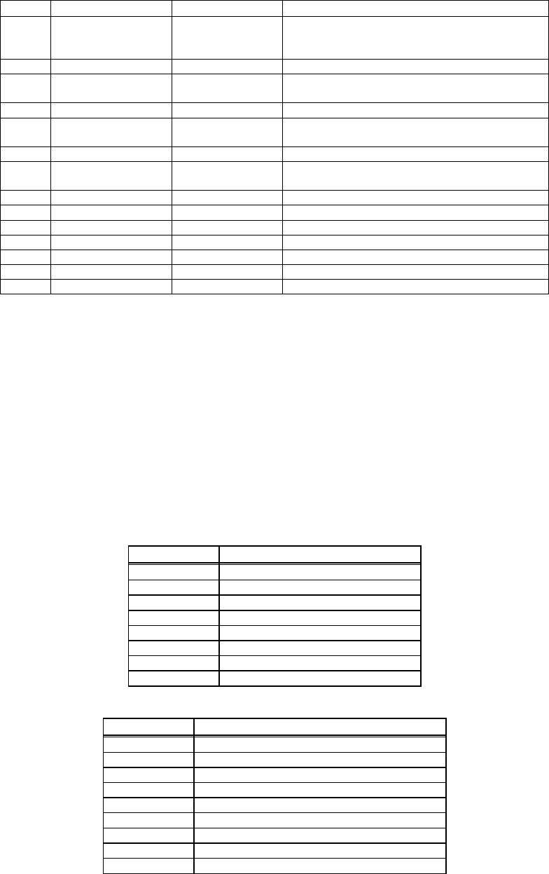
Front Panel Port Signals
RJ45 Pin # RS-232 Signal
1 RD+ (Ethernet)
2 RD- (Ethernet)
3 TD+ (Ethernet)
4 NC
5 NC
6 TD- (Ethernet)
7 NC
8 NC
Front Panel RS232 Cable Adapter
RJ45 Pin # RS232 DB9 / Female
1 NC
2 TXD (RS232) (Host PA9)
3 RXD (RS232) (Host PA8)
4 NC
5 GND
6 Ext_Trigger_In (DSP IRQ1)
7 NC
8 GND
9 Ext_Trigger_Out (DSP PA20)