
User's Manual


Table Of Contents
APPLICANT: MOTOROLA EQUIPMENT TYPE: ABZ89FC5812
User / Operational Manual
Functional Description / Operation of Modules and Interconnect (Draft)
EXHIBIT D1-6
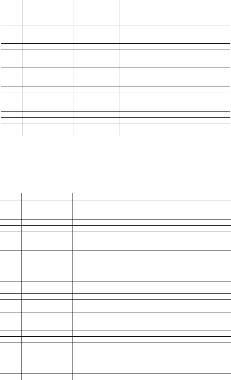
Pin # Signal Type Function/Notes
Fract-N. See DSP SPI section for
address decoding.
70 GND
71 SPI Addr1 Output SPI Addr signal for Abacus3s, Metering,
tunable filters, and LV Fract-N. See DSP
SPI section for address decoding.
72 GND
73 SPI Addr0 Output SPI Addr signal (LSB) for Abacus3s,
Metering, tunable filters, and LV Fract-N.
See DSP SPI section for address decoding.
74 GND
75 Noise_Cntl_1 Output To RCVR from FPGA GPIO2_0
76 GND
77 SYNCB Output Reset SSI data
78 GND
79 GND
80 GND
81 16.8MHz_ref
82 GND
83 GND
84 GND
RF Board Exciter Interconnect
The XCVR Control board interfaces to the RF board Exciter interface via a ribbon cable. The signals going to the
RF board Exciter’s interface are shown in Table 8.9.
RF Board Exciter Interconnect
Pin # Signal Type Function/Notes
1 Exciter_PWDN Shuts off power to Exciter
2 GND
3 RXD Receive data for PSM (to Host SCC3)
4 GND
5 RCLK Receive Clock for PSM (to Host SCC3)
6 GND
7 RFS Frame Sync for PSM (to Host SCC3)
8 GND
9 PSM_ACQ
10 GND
11 Exc_Tmhk_
Resetx
Output Alt_Resetx AND’ed Exc_Tmhk_Resetx
(From Host PC31)
12 GND
13 Exc_Jav_Resetx Alt_Resetx AND’ed Exc_Jav_Resetx
(From Host PC27 )
14 GND
15 Spare
16 GND
17 Javelin TSLOT/Tx
Enable
Output Exciter, GPIO from MSC8101 (Pin PA23).
Note PA22 reserved for TSLOTB if
differential signaling is used
18 GND
19 GND
20 GND
21 SCF_2X_CLK
22 GND
23 SCF_CLK From FPGA
24 GND