
User's Manual

SM User Manual Draft for Re
g
ulator
y
Review Pa
g
e 8 of 33
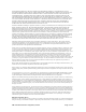
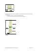
Eth ernet
Cabl e
Base Cover
Rel eas e
Le ve r
Base Cover
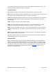
FIGURE 1
Remove the base cover as shown in FIGURE 1 to access the Ethernet connection and to view the
LED indicators.
• The RJ-45 connector is used to attach the Ethernet cable.
• The LED’s indicate system status and can be used for alignment.
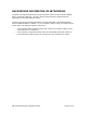
Et he rne t
Ca b l e
Canopy SM
RJ45
Co nn ect or
Conn ec tion
LEDs
Base Cover
FIGURE 2