
User's Manual


SM User Manual Draft for Re
g
ulator
y
Review Pa
g
e 17 of 33
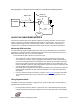
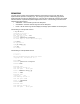
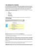
RJ-45 Crossover:
pin 1 → white / orange ← pin 3
pin 2 → orange ← pin 6
pin 3 → white / green ← pin 1
pin 4 → blue ← pin 4
pin 5 → white / blue ← pin 5
pin 6 → green ← pin 2
pin 7 → white / brown ← pin 7
pin 8 → brown ← pin 8
7
8
TX+
TX-
RX+
RX-
3
6
1
4
5
2
7
8
RX+
RX-
TX+
TX-
1
2
3
4
5
6
+V
return
+V
+V
+V
return
Pin PinRJ-45 Crossover
Pins 4, 5, 7, and 8 are used to carry power to the Canopy modules.