C a n o py T M Subscriber Module USER MANUA L SM02-UM-en Draft for Regulatory Review December 2003 © 2003 Motorola, Inc. All rights reserved. Printed in the U.S.
NOTICES Important Note on Modifications Intentional or unintentional changes or modifications to the equipment must not be made unless under the express consent of the party responsible for compliance. Any such modifications could void the user’s authority to operate the equipment and will void the manufacturer’s warranty. U.S. Federal Communication Commision (FCC) and Industry Canada (IC) Notification This device complies with part 15 of the U. S.
Canopy can be configured to operate at a range of frequencies, but at this time, only channels from 5745 MHz through 5805 MHz of the 5.7 GHz product have been tested for compliance with relevant EC directives. Before configuring equipment to operate outside this range, please check with your regulator. Exposure Note A Canopy module must be installed to provide a separation distance of at least 20 cm (7.9 in) from all persons.
THIS LIMITED WARRANTY IS THE ONLY WARRANTY PROVIDED BY MOTOROLA, AND MOTOROLA AND ITS LICENSORS EXPRESSLY DISCLAIM ALL OTHER WARRANTIES, EITHER EXPRESS OF IMPLIED, INCLUDING BUT NOT LIMITED TO IMPLIED WARRANTIES OF MERCHANTABILITY AND FITNESS FOR A PARTICULAR PURPOSE AND NONINFRINGEMENT. MOTOROLA DOES NOT WARRANT THAT THE OPERATION OF THE SOFTWARE WILL BE UNINTERRUPTED OR ERROR-FREE, OR THAT DEFECTS IN THE SOFTWARE WILL BE CORRECTED.
unit, without charge for parts or labor. IN NO EVENT SHALL MOTOROLA BE LIABLE TO YOU OR ANY OTHER PARTY FOR ANY DIRECT, INDIRECT, GENERAL, SPECIAL, INCIDENTAL, CONSEQUENTIAL, EXEMPLARY OR OTHER DAMAGE ARISING OUT OF THE USE OR INABILITY TO USE THE PRODUCT (INCLUDING, WITHOUT LIMITATION, DAMAGES FOR LOSS OF BUSINESS PROFITS, BUSINESS INTERRUPTION, LOSS OF BUSINESS INFORMATION OR ANY OTHER PECUNIARY LOSS, OR FROM ANY BREACH OF WARRANTY, EVEN IF MOTOROLA HAS BEEN ADVISED OF THE POSSIBILITY OF SUCH DAMAGES.
TABLE OF CONTENTS GETTING STARTED ............................................................................................. 8 Welcome ........................................................................................................................ 8 Features......................................................................................................................... 8 Intended Use...........................................................................................................
GETTING STARTED WELCOME Congratulations on the purchase of the Canopy subscriber module from Motorola! The Canopy subscriber module is the latest innovation in high-speed wireless networking that lets you easily network at high speeds. FEATURES The following is a subset of features included with your Canopy subscriber module: ♦ Broadband network speeds. ♦ Small, compact design. ♦ No special setup on your PC. INTENDED USE This manual is intended to be used with Canopy software release version 3.
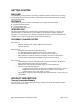
Base Cover Base Cover Release Ethernet Lever Cable FIGURE 1 Remove the base cover as shown in FIGURE 1 to access the Ethernet connection and to view the LED indicators. • The RJ-45 connector is used to attach the Ethernet cable. • The LED’s indicate system status and can be used for alignment.
The Connection LEDs report information about the current status of the subscriber module. The following descriptions explain the function of each LED. Operational Mode When looking at the LEDs on the module the following descriptions go from left to right. LNK: The link LED displays the status of the Ethernet link to the Canopy module. The LED will be constantly lit if there is an Ethernet link present. The LED is colored green.
BACKGROUND INFORMATION ON NETWORKING Computers are assigned IP addresses by network operators, which have two methods available, static or dynamic IP addressing. The user of this document will need to understand how IP addressing is done at their particular location. All Canopy radio products (Subscriber Modules, Access Point Modules, and Backhaul Modules) have the default IP address of 169.254.1.1.
INSTALLATION The following steps are required to install the Canopy subscriber module. • Unpack the Canopy products • Configure the subscriber module for the Canopy network • Install the module • Align the module UNPACK THE CANOPY PRODUCTS Upon receipt, carefully inspect all shipping boxes for signs of damage. If there is damage, immediately notify the transportation company. Unpack equipment, making sure that all ordered components have arrived. It is recommended that you save all the packaging materials.
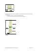
module should be mounted to the reflector in the following manner. The reflector arm is molded to receive the plastic housing of the subscriber module. Use stainless steel hose clamps to secure the module to the arm. The module is now properly aligned within the reflector. Stainless steel hose clamps Reflector dish arm INSTALLATION OF THE SUBSCRIBER MODULE When power is applied to a Canopy module or the unit reset via the web-based interface, the module will take approximately 25 seconds to boot up.
Stainless Steel Hose Clamps or any Suitabll e Equivalen nt Typical Antenna Mast FIGURE 3 • Leave the unit mounting means loose enough to allow for movement when performing the alignment procedure. They must be tightened after the alignment procedure is completed.
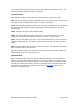
Wiring Diagram of Canopy subscriber module to Computer with Surge Suppressor outside wall Ethernet cable Ethernet cable SM 300SS Computer to NIC 24 VDC to Canopy wall adapter 10 AWG CU wire grounding system ALIGN THE SUBSCRIBER MODULE There are two methods that can be utilized for aligning a subscriber module to an access point module. The first is to monitor the RSSI and Jitter values on the subscriber. The second is to utilize the built-in alignment tool on the subscriber module.
IF USING A 5.7 GHz SUBSCRIBER MODULE or a “Low Power” 5.2 GHz Subscriber Module: the passive reflector will change the radiated pattern to 6° horizontal by 6° vertical. I F USING A 2.4 GHz SUBSCRIBER MODULE: the passive reflector will change the radiated pattern to 17° horizontal by 17° vertical. • Set the web page to auto-refresh (see Configuration section for further information) • Go to Alignment web page. Ensure that “RSSI Only Mode” is disabled. • Click “Enable Aiming Mode” button.
CABLING The RF environment the Subscriber Module operates in often will permit use of unshielded cable. However, in cases where cable interference issues are suspected, or as part of A/B comparisons to debug field problems, use of shielded cable with Subscriber Modules may be warranted. It is strongly recommended to use shielded cable for all Canopy infrastructure cabling associated with Backhauls, Access Points, and Cluster Management Modules.
RJ-45 Crossover: pin 1 → pin 2 → pin 3 → pin 4 → pin 5 → pin 6 → pin 7 → pin 8 → white / orange orange white / green blue white / blue green white / brown brown Pin ← pin 3 ← pin 6 ← pin 1 ← pin 4 ← pin 5 ← pin 2 ← pin 7 ← pin 8 RJ-45 Crossover Pin TX+ 1 3 RX+ TX- 2 6 RX- RX+ 3 1 TX+ 4 4 5 5 +V +V RX- 6 +V return 2 TX- 7 7 8 8 +V return Pins 4, 5, 7, and 8 are used to carry power to the Canopy modules.
ADVANCED FEATURES These features may be utilized in the Canopy System but are not required for basic operation. SECURITY - DES ENCRYPTION Standard Canopy modules provide Data Encryption Standard (DES) encryption. DES is a secret key encryption scheme using a 56 bit key. The basics of DES are that it performs a series of bit permutations, substitutions, and recombination operations on blocks of data using a secret key.
BRANDING On each Canopy module, the web-based interface screens have a Canopy logo that can be replaced with an operator’s company logo. The Canopy logo file is called canopy.jpg and the replacement file must also be called canopy.jpg. The new file is transferred via FTP to the module and then added to a special filesystem through a telnet session.
THE INTERFACE SCREENS The Canopy subscriber module contains a series of web pages that are used to interface to the unit. The following is a quick reference to interface screens. Note: These screens are subject to change by subsequent software versions. To access the web based interface you first must be on a computer that is in some way connected to the subscriber module. This can be done either directly or through a network. Enter the IP address of the subscriber module (default is 169.254.1.
Uptime: displays the length of time the module has been operating since a rest of the module occurred. System Time: displays the current time, which is inherited from the Canopy System via the registration to an access point module. When the module is registered to a Canopy System where a Cluster Management Module (CMM) is being utilized the time is displayed in Greenwich Mean Time (GMT). Ethernet Interface: displays the configuration of the Ethernet interface on the module.
CONFIGURATION The Configuration webpage contains information and configurable parameters pertaining to the operation of the product. The first line of information on the Configuration screen is a repeat of the Device Type from the Status web page. The following are the parameters and their descriptions. Link Negotiation Speeds: choose the type of link speed desired for the Ethernet connection. The default for this parameter is for all the choices to be checked.
accessible via the host computer (network) that is connected to the module via the Ethernet cable. If the address is designated a public address it will be accessible network-wide. The default for this feature is for the address to be local. If the IP address is forgotten, the operator will need physical access to the module and will need to create a Canopy “default plug”. See steps at the end of this section for creation and use of a default plug.
set the supplied information into the sysName SNMP MIB-II object and can be polled by a SNMP management server. The buffer size for this field is 128 characters. Site Contact: enter contact information relating to the module. This parameter will set the supplied information into the sysContact SNMP MIB-II object and can be polled by a SNMP management server. The buffer size for this field is 128 characters. Site Location: enter information relating to the physical location of the module.
EVENT LOG This page contains information that is recorded from the subscriber module for troubleshooting purposes. Please make note of the information that is gathered here when calling for technical support. Clear Event Log: this button will clear the event log.
AP EVAL DATA The AP Eval Data web page contains information on each of the access point modules that the subscriber module has visibility to. For each access point module that can be seen certain bits of information are shown on this web page.
ETHERNET STATS The Ethernet Stats web page reports TCP throughput and error information for the Ethernet connection of the subscriber module. The following definitions are available: inoctets count: displays the total number of octets received on the interface, including framing characters. inucastpkts count: displays the total number of subnetwork-unicast packets delivered to a higher layer protocol innucastpkts count: displays the total number of non-unicast (i.e.
bit times, then it is considered a late collision. A late collision should be taken as a serious network problem, since it causes the frame being transmitted to be discarded. The most common cause of late collisions is a mismatch between duplex configurations at each end of a link segment. RetransLimitExp: displays the total number of retransmit limit expirations. TxUnderrun: displays the total number of transmission-underrun errors on the Ethernet controller.
To perform a link test enter a number into the field labeled “Duration”. The duration is the number of seconds the RF link will be tested. Start the link test by clicking the “Start Test” button. The test will now run for the set duration. If the web page is not set to automatically refresh, click the “Refresh Display” button to see the results.
time. If a Canopy module is placed into Alignment Mode it will automatically drop into Operational Mode after 15 minutes. BER Display Bit Error Rate (BER) Display is utilized by the operator to measure the amount bit errors present in a link. BER Display will only work if the access point module is configured to send the BER stream. **IMPORTANT** If one access point module in a cluster is set to send a BER stream then all other access point modules in that cluster must be configured in the same fashion.
connecting these modules.
APPENDIX There are two basic concepts that are needed for a basic understanding of networking, IP addresses and subnet masks. IP addresses are 32-bit binary numbers that have two corresponding parts or sub-addresses, the first part identifying the network and the second part identifying the hosts on the network. An imaginary boundary separates the first part from the second. This imaginary boundary is marked by way of the subnet mask.
SPECIFICATIONS Frequency Band Ranges 2.4 Modules: ISM 2.4 to 2.4835 GHz 5.2 Modules: U-NII: 5.25 to 5.35 GHz 5.7 Modules: ISM: 5.725 to 5.