
User's Manual

Installing the Expansion Cabinets Chapter 5: Installing the Digital Simulcast Remote Site (10Base-2)
For a standard installation, the equipment cabinet is located adjacent to the power supply
equipment with a cable loop length less than 10.67 m (35 ft.).
The “loop length” refers to the combined length of the -48 VDC lead and the DC return lead.
For example, a cabinet which needs 4.87 m (16 ft.) of wire between the power supply equipment
and equipment cabinets has a total loop length of 9.75 m (32 ft.).
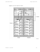
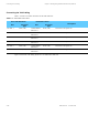
Table 5-3 lists the required wire sizes for various installations.
Table 5-3 Power Connections Wire Size
Loop Length
Wire Size
15.2m(50ft.) orless 16mm
2
CSA (5 AWG)
15.2 - 24.8 m (50 - 80 ft.) 25 mm
2
CSA (4 AWG)
24.8 - 36.6 m (80 - 120 ft.) 35 mm
2
CSA (2 AWG)
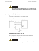
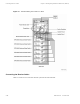
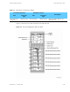
Installing the Expansion Cabinets
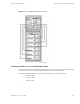
If an expansion cabinet is required, the expansion cabinet must be located to the right of the prime cabinet
(Se
e Figure 5-5). The two cavity combiners are connected to their respective side of the phasing harness.
The phasing harness bracket for the transmit combiner is mounted to the expansion rack. The power
monitor unit (PMU) is connected to the post filter, which is connected to the top of the phasing harness.
5-10
68P81003Y71-O November 2002