
User's Manual
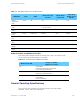
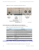
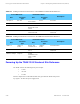

Simulcast Hardware Installation ALARM INDICATION (NO LOCK ON GPS SIGNAL)
ALARM INDICATION (NO LOCK ON GPS SIGNAL)
A system alarm indicates when the GPS signal cannot be located and that the
antenna may need to be repositioned.
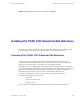
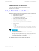
Cabling the TRAK 9100 Simulcast Site Reference
All output signal connections interfacing to the network are made via the rear panel. The connections are:
• Two power supply (AC or DC) connectors
• Two GPS antenna N-type connectors
• An RJ45 connector for 10Base-T to distribute Coordinated Universal Time
(UTC) through Network Time Protocol (NTP)
• An RJ45 connector for Alarm (relay contacts) reporting
• A DB9 connector for Time of Day (TOD) output
• An RS232 DB9 connector for diagnostics (VT100)
• An IEEE-488 connector for digital distribution unit (DDU) TRAK 9200
• 24 BNC connectors for:
• 1 pps
• 5Mpps
• 1 pps + 5 Mpps composite signals, framed 1.544/2.048 Mbps TTL, and IRIG-B (or 10
MHz if desired) outputs depending on the type of modules plugged at the front panel.
All cables are connected between the BNC T-adapters, which are mounted
to the appropriate module connector.
The cabinet is equipped with cables (index no. 2) and T-adapters for connection to six base
radios regardless of BR complement. Unused T-adapters are left unconnected.
Unless the cabinet is to be used with other RF cabinets, 5 MHz/1 pps OUT
connector must be terminated with a 50 ohm terminator.
Table 5-21 lists all of the cables from the front connections on the TRAK 9100 simulcast site reference.
Table 5-22 lists the cables from the connections on the back of the TRAK 9100.
68P81003Y71-O November 2002 5-29