C a n o py TM Backhaul Module USER MANUA L BH02-UM-en May 2003 © 2003 Motorola, Inc. All rights reserved. Printed in the U.S.
NOTICES Important Note on Modifications Intentional or unintentional changes or modifications to the equipment must not be made unless under the express consent of the party responsible for compliance. Any such modifications could void the user’s authority to operate the equipment and will void the manufacturer’s warranty. U.S. Federal Communication Commision (FCC) and Industry Canada (IC) Notification This device complies with part 15 of the U. S.
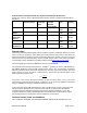
Product Details for Products Tested for Compliance with Relevant EC Directives (At this time, only the 5.725 to 5.825 GHz product has been tested for compliance with relevant EC directives.) Effective Modulation Channel Operating Maximum Isotropic Type Spacing Frequency Range Transmitter Radiated Power Power (EIRP) Access Point 5.725 to 5.825 GHz 200mW RMS 1 Watt EIRP High Index 25 MHz BFSK 20 MHz Subscriber Module Subscriber Module with Reflector Backhaul 5.725 to 5.
ACCEPT THE TERMS OF THIS LICENSE. BY BREAKING THE SEAL ON THIS DISK KIT / CDROM, OR IF YOU USE THE SOFTWARE OR RELATED PRODUCT, YOU ACCEPT THE TERMS OF THIS LICENSE AGREEMENT. IF YOU DO NOT AGREE TO THESE TERMS, DO NOT USE THE SOFTWARE OR RELATED PRODUCT; INSTEAD, RETURN THE SOFTWARE TO PLACE OF PURCHASE FOR A FULL REFUND. THE FOLLOWING AGREEMENT IS A LEGAL AGREEMENT BETWEEN YOU (EITHER AN INDIVIDUAL OR ENTITY), AND MOTOROLA, INC. (FOR ITSELF AND ITS LICENSORS).
SOFTWARE WILL BE CORRECTED. NO ORAL OR WRITTEN REPRESENTATIONS MADE BY MOTOROLA OR AN AGENT THEREOF SHALL CREATE A WARRANTY OR IN ANY WAY INCREASE THE SCOPE OF THIS WARRANTY. MOTOROLA DOES NOT WARRANT ANY SOFTWARE THAT HAS BEEN OPERATED IN EXCESS OF SPECIFICATIONS, DAMAGED, MISUSED, NEGLECTED, OR IMPROPERLY INSTALLED. BECAUSE SOME JURISDICTIONS DO NOT ALLOW THE EXCLUSION OR LIMITATION OF IMPLIED WARRANTIES, THE ABOVE LIMITATIONS MAY NOT APPLY TO YOU. Limitation of Remedies and Damages.
U.S. Government Users. If you are a U.S. Government user, then the Software is provided with "RESTRICTED RIGHTS" as set forth in subparagraphs (c)(1) and (2) of the Commercial Computer Software-Restricted Rights clause at FAR 52 227-19 or subparagraph (c)(1)(ii) of the Rights in Technical Data and Computer Software clause at DFARS 252.227-7013, as applicable. Disputes.
http://www.motorola.com/canopy TABLE OF CONTENTS GETTING STARTED ............................................................................................. 9 Welcome ........................................................................................................................ 9 Intended Use.................................................................................................................. 9 Document Change History....................................................................
Configuration Page....................................................................................................... 41 Event Log..................................................................................................................... 43 AP Eval Date................................................................................................................ 43 Ethernet Stats ..............................................................................................................
GETTING STARTED Welcome Thank you for your purchase of a Motorola Canopy Backhaul module. This new technology is the latest innovation in high speed wireless networking. Some of the Canopy system features are: - Network speeds of 10/100 BaseT - Small compact design - No special set up on your PC. Intended Use This manual is intended to be used with Canopy software release version 3.x or greater. The intended audience for this manual is system operators and equipment installers.
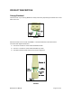
PRODUCT DESCRIPTION Canopy Backhaul The base cover of your Canopy Backhaul is easily removed by depressing the release lever on the back of the cover. Base Cover Base Cover Release Lever Ethernet Cable FIGURE 1 Remove the base cover as shown in FIGURE 1 to access the Ethernet connection and the Connection LED alignment indicators.
The diagnostic LEDs report information about the current status of the access point module. following descriptions explain the function of each LED. The Operational Mode LNK: The link LED displays the status of the Ethernet link to the Canopy module. The LED will be constantly lit if there is an Ethernet link present. The LED is colored green. ACT/4: The activity LED displays the status of any data activity on the Ethernet link.
BACKGROUND INFORMATION ON NETWORKING Computers are assigned IP addresses by network operators, which have two methods available, static or dynamic IP addressing. The user of this document will need to understand how IP addressing is done at their particular location. All Canopy radio products (Subscriber Modules, Access Point Modules, and Backhaul Modules) have the default IP address of 169.254.1.1.
SYSTEM OVERVIEW AND SITE PLANNING Definitions: Backhaul Timing Master – a module that is used in a point-to-point link. This module controls the air protocol and configurations for the link. Backhaul Timing Slave – a module that is used in a point-to-point link. This module accepts configuration from the master module. Cluster Management Module – a module that contains power, GPS timing, and networking for backhaul timing master(s). Can also be utilized in conjunction with an access point cluster.
From these diagrams it can be seen that at each location there is only like kind backhaul modules. In all cases where there is a cluster management module an access point cluster could be placed also. In the case of Example 2, a cluster management module could be placed where the two backhaul timing slaves are located to install an access point cluster; however the timing slaves do not need to be connected to he CMM for timing purposes.
GENERAL CONSIDERATIONS • Fresnel Loss - The Fresnel Zone is a theoretical area around the line of sight of an antenna transmission that can affect the signal strength. Objects that penetrate the Fresnel Zone can cause fading of the transmitted signal. This fading is caused by the cancellation of the signal due to out-of-phase reflections. An unobstructed line of sight is important, but it is not the only determination of an adequate placement.
CHANNEL PLANS Whether using 5.2 GHz or 5.7 GHz modules, frequencies should never be placed closer than 20 MHz. The Canopy modules allow the operator to chose frequencies every 5 MHz. This is so that in the event of co-location with other equipment the operator can customize the channel layout for interoperability. 5.2 GHz Recommended Frequencies The following are the 3 non-overlapping channels that are recommended by the Canopy team for use with the backhaul module: • 5.275 GHz • 5.300 GHz • 5.
NETWORKING INFORMATION The Canopy access point module will each utilize an IP address on the operator’s network. It is recommended that the access point modules never be placed directly onto the Internet. IP addresses may be assigned sequentially clockwise around an access point cluster for easier manageability. The operator will also need to identify the appropriate subnet mask and network gateway each of the modules.
REFLECTOR DISHES The Canopy backhaul system can create a point-to-point links within the following distances: Configuration Distance Both ends of the link using the internal patch antennas 2 miles (3.2 km) One end of the link using a Canopy passive reflector 10 miles (16 km) Both ends of the link using Canopy passive reflectors 35 miles (56 km) The passive reflector arm is molded to receive the plastic housing of the backhaul module. Use stainless steel hose clamps to secure the module to the arm.
ADVANCED FEATURES These features may be used in the Canopy System but are not required for basic operation. DES ENCRYPTION DES (Data Encryption Standard) is a secret key encryption scheme. The basics of DES are that it performs a series of bit permutations, substitutions, and recombination operations on blocks of data utilizing a secret key.
Telnet +> clearwebfile Telnet+> lsweb Flash Web files free directory entries: 32 free file space 64336 bytes SNMP Simple Network Management Protocol (SNMP) can be utilized to monitor the Canopy modules. The standard MIB-II (systems and interfaces) objects are programmed into the modules. For specific information on this MIB see RFC 1213 for details.
INSTALLATION The following steps are required to install the Canopy backhaul module: • Unpack the Canopy products • Configuration of the backahaul modules • Installation of the backhaul modules • Alignment UNPACK THE CANOPY PRODUCTS Upon receipt, carefully inspect all shipping boxes for signs of damage. If there is damage, immediately notify the transporatation company. Unpack equipment, making sure that all ordered components have arrived. It is recommended that you save all the packing materials.
module so that it can register with a backhaul timing master module. The color codes must match. The operator can prevent unauthorized users from connectig to the backhaul module’s web based interface by assigning a password. There is no default password and password protection is turn off is turn off from the factory. Passwords can be from 1 to 16 characters. Any combination of characters is allowed, except for these special characters: “ , . ‘ { } / \ ; : [ ] ( ) ` ~ NOTE: If the operator forgets either
• Replace the base cover on all of the backhaul modules. ALIGNMENT • If the backhaul modules are not utilizing passive reflectors, then visually align the units. • If the backhaul modules are utilizing passive reflectors then visually align if possible or utilize compass headings and initiate step 1 in the following process: 1. Lock down timing master module 2.
CABLING The following information describes the wiring standards for installing a Canopy system. All diagrams use the EIA/TIA 568B color standard. Currently shipping modules auto-sense the Ethernet cable type – either RJ-45 straight-thru cable or RJ-45 crossover cable can be used to connect a network interface card (NIC), hub, router, or switch to a module. Earlier modules did not auto-sense.
Pin pin 1 → white / orange pin 2 → white / green pin 3 → white / blue pin 4 → green pin 5 → blue pin 6 → orange the 4th pair is not used Backhaul User Manual ← pin 1 ← pin 2 ← pin 3 ← pin 4 ← pin 5 ← pin 6 1-pps 1 RJ-11 Straight-Thru Pin 1 1-pps TX+ 2 2 RX+ RX+ 3 3 TX+ not used 4 4 5 5 not used gnd 6 6 gnd not used not used Page 25 of 50
THE INTERFACE SCREENS The Canopy backhaul module contains a series of web pages that are used to interface to the unit. The following is a quick reference to interface screens. Note: These screens are subject to change by subsequent software versions. To access the web based interface you first must be on a computer that is in some way connected to the access point module. This can be done either directly or through a network. Enter the IP address of the backhaul module (default is 169.254.1.
THE TIMING MASTER QUICK START The Canopy System consists of a family of highly flexible, fixed wireless access devices that can be put into service quickly and with a minimal configuration. The Quick Start is a wizard that walks the operator through that configuration.
STATUS PAGE The Status page contains information on the operation of the product. It is the default web page. The following parameters are displayed: Device Type: displays the type of Canopy module that is currently being viewed. This field will let the operator know the frequency band of the module, the protocol that it is utilizing, and the MAC address of the module. The frequency band can either be in the 5.2 GHz or 5.7 GHz band.
• ERROR: No Sync Pulse: If the module is set to receive a sync pulse from an outside source (not itself) and it is currently not receiving the pulse this message will be displayed. When this message is displayed the access point module will turn its transmitter off so as to not create any self-interference within the Canopy System. Radio Slicing Value: displays information to be used be Canopy technical support. Radio Transmit Gain Setting: displays information to be used by Canopy technical support.
CONFIGURATION The Configuration web page contains information and configurable parameters pertaining to the operation of the product. The first line of information on the Configuration screen is a repeat of the Device Type from the Status web page. The following are the parameters and their descriptions. Timing Mode: choose whether this module will be a timing master or a timing slave. If the operator is changing this mode, change only this parameter, save the changes and reboot.
default for this parameter is 75%. LAN 1 IP: enter in the IP address that will be associated with the Ethernet connection on this module. The default address is 169.254.1.1. If the IP address is forgotten, the operator will need physical access to the module and will need to create a Canopy “default plug”. See steps at the end of this section for use of a default plug. LAN1 Subnet Mask: enter in an appropriate subnet mask for the module to “talk” on the network. The default value for this parameter is 255.
Full Access: enter the same password in both fields for verification. The full-access password, when used, will allow view and change activities to the module. When the full-access password is set, the password will also be tied to telnet and FTP sessions to the module. When prompted for the password via the web-based interface, there is no username required; however when prompted for the password via a telnet or FTP session, the user that MUST be used is “root”.
set the supplied information into the sysName SNMP MIB-II object and can be polled by a SNMP management server. The buffer size for this field is 128 characters. Site Contact: enter contact information relating to the module. This parameter will set the supplied information into the sysContact SNMP MIB-II object and can be polled by a SNMP management server. The buffer size for this field is 128 characters. Site Location: enter information relating to the physical location of the module.
EVENT LOG This page contains information that is recorded from the subscriber module for troubleshooting purposes. Please make note of the information that is gathered here when calling for technical support. Clear Event Log: this button will clear the event log. LUID SELECT This web page connects to a registered unit over the RF link, to view its internal webpages. The Sessions webpage determines which LUID corresponds to a specific unit.
LINK TEST The Link Test is a test for measuring the throughput and efficiency of the RF link between two Canopy modules. To perform a link test enter a number into the field labeled “Duration”. The duration is the number of seconds the RF link will be tested. Start the link test by clicking the “Start Test” button. The test will now run for the set duration. If the web page is not set to automatically refresh, click the “Refresh Display” button to see the results.
SESSIONS The Session web page contains information on each of the subscriber modules that has registered to the access point module. For each of the subscriber modules certain bits of information are shown on this web page. An example of such information is: LUID: 002 : MAC: 0a-00-3e-00-02-2f State: IN SESSION Software Version : CANOPY 3.
Average Jitter: displays the average Jitter value for the subscriber module. Last Jitter: displays the last Jitter value for the subscriber module. GPS STATUS The GPS Status web page displays information about latitude, longitude, height, satellites seen and tracked when the access point module is configured to sync to received signal and is connected to a Cluster Management Module.
EthBusErr: displays the total number of Ethernet bus errors on the Ethernet controller. CRCError: displays the total number of CRC errors on the Ethernet controller. RxOverrun: displays the total number of receiver-overrun errors on the Ethernet controller. Late Collision: displays the total number of late collisions on the Ethernet controller. A normal collision occurs during the first 512 bits of the frame transmission. If a collision occurs after the 512 bit times, then it is considered a late collision.
THE TIMING SLAVE STATUS The Status page contains information on the operation of the product. It is the default web page. The following parameters are displayed: Device Type: displays the type of Canopy module that is currently being viewed. This field will let the operator know the frequency band of the module, the protocol that it is utilizing, and the MAC address of the module. The frequency band can either be in the 5.2 GHz or 5.7 GHz band. The protocol for a subscriber module must be multipoint.
• • • • an access point module. Syncing – module is attempting to synchronize timing to a single access point module Registering – module sent a request for registration and is awaiting a response Registered – module is locked on to a specific access point module and ready to transmit and receive data packets Alignment – module is in alignment mode RSSI: displays the current value for the Radio Signal Strength Indicator.
CONFIGURATION PAGE The Configuration web page contains information and configurable parameters pertaining to the operation of the product. The first line of information on the Configuration screen is a repeat of the Device Type from the Status web page. The following are the parameters and their descriptions. Timing Mode: choose whether this module will be a timing master or a timing slave. If the operator is changing this mode, change only this parameter, save the changes and reboot.
Default Gateway: enter in an appropriate gateway address for the module. The default value for this parameter is 169.254.0.0. Color Code: enter in a value (0-254). The color code on the subscriber module and the access point module must match in order for registration to occur. Color code is not a security feature. It is a means for the Canopy System operator to segregate an individual network or neighbor Canopy networks.
SNMP management server. The buffer size for this field is 256 characters. Save Changes: by clicking on this button, any changes that have been made on the Configuration page will be committed to flash memory and will take effect after the next module reboot. Undo Save Changes: by clicking on this button, any changes that have been made and not committed through a reboot of the module.
Out of Range: displays a counter for the number of times the access point module has seen a subscriber module who has attempted to register and has been farther away than the max range parameter on the access point. Sector ID: displays the sector ID of the access point module. Color Code: displays the color code of the access point module. Sector User Count: displays the numbers of registered subscriber modules on the access point.
Link Test The Link Test is a test for measuring the throughput and efficiency of the RF link between two Canopy modules. To perform a link test enter a number into the field labeled “Duration”. The duration is the number of seconds the RF link will be tested. Start the link test by clicking the “Start Test” button. The test will now run for the set duration. If the web page is not set to automatically refresh, click the “Refresh Display” button to see the results.
Alignment The Alignment web page contains tools to assist in the alignment of a subscriber module to an access point module. There are two modes that can be utilized when aligning a module: 1) RSSI only and 2) normal alignment mode. RSSI Only is a mode where the module will report the signal strength based on the amount of energy present at a selected frequency. The subscriber module does not have to be registered to an access point module for information on signal strength to be reported back.
any one of these criteria are not met the link may still be operational but may have issues time to time. Note: If a Canopy module is placed into Alignment Mode it will automatically drop into Operational Mode after 15 minutes. BER Display Bit Error Rate (BER) Display is utilized by the operator to measure the amount bit errors present in a link. BER Display will only work if the access point module is configured to send the BER stream.
ACCESSORIES The following accessories are available for use with the Canopy System. To purchase accessories, please contact an authorized Canopy dealer, unless otherwise noted. • Universal mounting bracket • Passive reflector dishes for use with 5.7 GHz subscriber modules. • 90-220V AC power supply (part number ACPSSW-01) Cable assemblies for the Canopy System can be ordered from Best-Tronics Manufacturing Inc. by going to their website at http://www.best-tronics.
APPENDIX There are two basic concepts that are needed for a basic understanding of networking, IP addresses and subnet masks. IP addresses are 32-bit binary numbers that have two corresponding parts or sub-addresses, the first part identifying the network and the second part identifying the hosts on the network. An imaginary boundary separates the first part from the second. This imaginary boundary is marked by way of the subnet mask.
SPECIFICATIONS Operating Frequency Range U-NII: 5.25 to 5.35 GHz and 5.725 to 5.825 Ghz ISM: 5.725 to 5.850 GHz Access Method TDD/TDMA Signaling Rate 10 Mbps or 20 Mbps Modulation Type High Index BFSK (Optimized for interference rejection) Carrier to Interference (C/I) also known as Jitter 3dB nominal Receiver Sensitivity -83dBm 10-4 BER Operating Range (All Weather) Up to 2 miles with integrated antenna. Up to 35 miles with installed passive reflectors.