
User's Manual

AP_CMM2 User Manual Pa
g
e 26 of 49
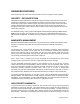
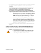
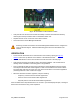
115/230 V switch
AC power
connectors
Fuse receptacle
Figure 7: Location of 115/230 V Switch
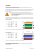
• The AC power connectors are labeled
- N for Neutral
- L for Line
- PE for Protective Earth (PE)
(ground)
• The maximum thickness wire to be used is 12 AWG (4 mm
2
).
INSTALLATION OF THE EQUIPMENT
The following tools may be needed during installation:
• 3/8” nut driver
• 12” adjustable wrench
• 7/16” wrench for installation of GPS mounting bracket
• 14mm wrench for installation of Cluster Management Module pole-mounting brackets
• Needle-nose pliers
When power is applied to a Canopy module or the unit reset via the web-based interface, the
module will take approximately 25 seconds to boot up. During this boot up time, power on self-
tests and other diagnostics are being performed.
The following steps are needed to install the Canopy equipment:
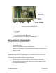
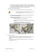
• Remove the base cover from all Canopy Access Point modules to be installed.
• Remove the GPS sync cable knockout from the base cover with needle-nose pliers.
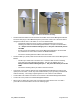
• Mount the Access Point modules: