
User's Manual
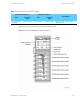
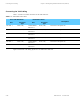
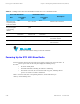
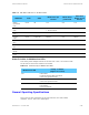
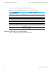
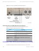
Table Of Contents

Simulcast Hardware Installation Status Priorities for Multifunction LEDs
Table 5-9 LED Status Indicators on the Base Radio
LED Name
Color Solid
Blinks Once per
Second
Blinks Twice
per Second
Solid Then
Blinks off 1/4
Second
Station
Operational
(ON)
Green
All N/A N/A N/A
Station Failure
(Fail)
Red FRU failure • Ext Ref Failure
• Rx Tx Unlock
Config N/A
Service/Tx Inhibit
(SVC)
Yellow N/A Service SVC Tx Inh N/A
Control
(CTL)
Green
Control Ch Failsoft N/A
ISP Rx
Rx Active
(Rx)
Green
Rx Active Illegal Rx N/A N/A
PA Full/PA Low
(PA)
Green
PA Active N/A N/A N/A
Station Disable
(StnD)
Red
FLASH
N/A N/A N/A
V. 2 4 L i n k
(V24)
Green
V24 Link V24 Fail N/A N/A
Status Priorities for Multifunction LEDs
Some LEDs perform multiple functions for the base radio. Table 5-10 lists these LEDs
and the order in which status indications are handled.
Table 5-10 Status Priority for Multifunction LEDs
Multifunction LED
Priority of Status
(Highest to Lowest)
Fail • FRU failure
• External reference failure and unlock
• Base radio operational mode
SVC
• Transmitter inhibited
• Base radio operational mode
StnD
• Software download
• PA inhibited
• Receiver inhibited
General Operating Specifications
This section provides specifications for the STR 3000 rack, base radio, RFDS,
transmitter, receiver, and receiver multicoupler.
68P81003Y71-O November 2002 5-19