
User's Manual
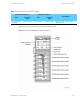
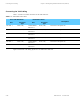
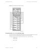
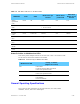
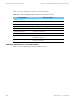
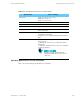
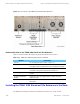
Table Of Contents

Powering Up the STR 3000 Base Radio Chapter 5: Installing the Digital Simulcast Remote Site (10Base-2)
Table 5-8 Cabling Connections from the STR 3000 Rack at a Co-Located Remote Site
From STR 3000 Rack
Destination Device
Port
Connection
Type
Port
Connectoin
Type
Description
Ethernet In port
on junction pa
nel
in the first cabinet
BNC
Port1onHub
BNC
Ethernet LAN connection
Ethernet In port on
the junction panel
of succeeding
cabinets
BNC
Ethernet out on
panel
BNC
Ethernet LAN connection
Last cabinet BNC with 50 ohm
termination
Terminator on
Ethernet Out
BNC with 50 ohm
termination
Ethernet LAN connection
Top of cabinet 7/16 DIN N Type Transmit antenna 7/16 DIN N Type Transmit output from the base radio to
the transmit antenna
Top of cabi
net
7/16 DIN N T
ype
Receive an
tenna
7/16 DIN N T
ype
Receive an
tenna input into the
STR 3000 rack
Both ends o
f the Ethernet cabling run must be terminated.
Powering
Up the STR 3000 Base Radio
Press the ON/OFF switch on the front of the power supply to apply power to the base radio. As
the radio
powers up, the LEDs on the front panel display the following activity:
• All LEDs initially blink.
• The SlnD LED blinks, indicating the software is initializing.
• After ab
out 10 seconds, the V.24 and ON LEDs stay green, indicating that the
power is on and the V.24 link is established.
Table 5-9 lists the LEDs, their corresponding functions, and the indications pro-
vided by various blinking states.
5-18
68P81003Y71-O November 2002