
User's Manual Part 2
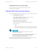
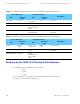
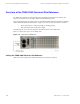
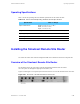
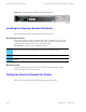
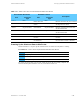
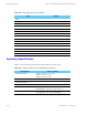
Table Of Contents

Simulcast Hardware Installation Powering Up the Simulcast Remote Site Router
Table 5-31 Cable Connections from the Simulcast Remote Site Router
From Remote Site Router
Destination Device
Port
Connector
Type
Port
Connector
Type
Description
LAN 1 RJ45
Remote Site Hub
RJ45
Ethernet connection only for co-located
LAN 2 RJ45
Remote Site
Switch
RJ45
Ethernet connection between the hub
and the prime site switch
Serial 3 60-pin FlexW
AN
Channel Bank 60-pin FlexW
AN
Ethernet con
nection between the hub
and the channel bank
Serial 4 60-pin FlexWAN Channel Bank 60-pin FlexWAN Ethernet connection between the hub
and the channel bank
WAN 5 RJ45
not used
RJ45
not used
WAN 6 RJ45
not used
RJ45
not used
Console RS232/DB9 Console/Termi-
nal, Serial
Port
RS232/DB9 Communications connection between
the router a
nd a console or terminal
P
owering Up the Simulcast Remote Site Router
Perform Procedure 5-7 to power up the simulcast remote site router and verify that it is working.
Procedure 5-7 How to Power Up the Simulcast Remote Site Router
1
Attach the power cable to the power receptacle.
2
Plug the power cable into the AC outlet.
3
Turn the power switch to the ON position.
4
Verify that the power LED is on.
The power-up process takes a few seconds. When the process has successfully completed, the
LEDs on the front panel should be on or off, as described in Table 5-32.
68P81003Y71-O November 2002 5-45