
User's Manual Part 2
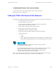
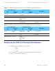
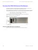
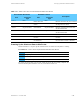
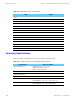
Table Of Contents

Overview of the TRAK 9200 Simulcast Site Reference Chapter 5: Installing the Digital Simulcast Remote Site (10Base-2)
Overview of the TRAK 9200 Simulcast Site Reference
The TRAK 9200 simulcast site reference differs from the TRAK 9100 simulcast site reference with
respect to two modules: the power supply and the termination/fault logic unit.
The power supply has only one output (5 VDC). So the indicators differ from those referenced in "Powering
Up the TRAK 9100 Simulcast Site Reference" on page 5-30. There are only two indicators, as follows:
• Green, indicating the 5 VDC power supply is operating properly.
• Red, indicating a fault with the power supply.
The fault logic unit serves the same function as the fault sense unit in the TRAK 9100.
Figure 5-11 shows the rear view of the TRAK 9200.
Figure 5-11 Rear View of TRAK 9200
Cabling the TRAK 9200 Simulcast Site Reference
Table 5-24 lists the cabling for the TRAK 9200 simulcast site reference expansion.
5-32 68P81003Y71-O November 2002