
User's Manual Part 2
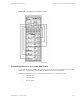
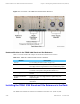
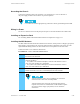
Table Of Contents

Simulcast Hardware Installation Grounding the Chassis
Grounding the Chassis
Connect the grounding cable to the ground lug. The ground lug is a screw on the back of
the power supply located to the left of the AC power receptacles.
Use 6 AWG wire and the appropriate lug connected to chassis ground through to the RGB.
Wiring for Power
The two AC outlets on the rear of the panel provide power to all of the modules in the TRAK 9100.
Installing an Expansion Rack
See "Installing TRAK 9200 Simulcast Site Reference for Expansion" on page 5-31.
Installing the GPS Antenna
The GPS antenna feeds the TRAK 9100 simulcast site reference, which provides a 5 Mpps/1 pps signal (5
Mpps signal at 1 pps repetition rate) to the base radios and other components at the remote site. This
signal establishes timing functions for the transmit and receive frequencies for the base radios.
Perform Procedure 5-2 to install the GPS antenna.
Procedure 5-2 How to Install the GPS Antennas
1 Mount the GPS
antenna with an unrestricted aerial down view to within 10˚ of
the horizon in all directions.
2
Mount the antennas high enough to clear the peak of the site roof using the
following guidelines:
• For systems in the northern hemisphere, mount the GPS antennas so that a
clear view of the southern sky is maintained.
• For systems in the southern hemisphere, mount the GPS antennas so that a
clear view of the northern sky is maintained.
3 Isolate the
GPS antennas from RF interference by mounting the antennas at a
distance of at least 3.66 m (12 ft.) horizontally from the other antennas.
4
Mount the GPS antennas to clear obstructions and provide a clear path.
Adjacent structures (such as trees or buildings) are considered
obstructions due to their wide and solid profiles.
Adjacent antenna towers at the RF site which protrude into the
required view (but have a minimal effect on GPS satellite reception
due to their narrow, largely open profiles) are not considered
obstructions.
68P81003Y71-O November 2002 5-27