
User's Manual Part 2
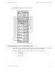
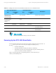
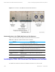
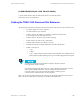
Table Of Contents

Hardware Modules in the TRAK 9100 Simulcast Site Reference Chapter 5: Installing the Digital Simulcast Remote Site (10Base-2)
Figure 5-9 Front View of the TRAK 9100 Simulcast Site Reference
Hardware Modules in the TRAK 9100 Simulcast Site Reference
Table 5-19 lists the modules that comprise the TRAK 9100 simulcast site reference.
Table 5-19 TRAK 9100 Simulcast Site Reference Modules
Module Description
Antenna
See "Installing the GPS Antenna" on page 5-27.
GPS Receiver (A1) This module contains a crystal oscillator and generates the 1 pps
and 5 Mpps reference signals based on received GPS timing signals.
GPS Receiver (A2) A second oscillator is included for redundancy. (Module A2 does
not include a front-panel cooling fan like Module A1.)
Power Supply Converts AC input to DC voltages used by all other TRAK 9100
modules.
Frequency Distribution
Module
Outputs the 1 pps and 5 Mpps reference signals along with
composite signal.
Fault Sense Unit Detects system failures and provides control, alarm, and status
information.
Installing the TRAK 9100 Simulcast Site Reference in the Rack
The TRAK 9100 simulcast site reference is installed in an EIA/TIA 19-in. (48.26 cm) rack.
5-26 68P81003Y71-O November 2002