
User's Manual Part 2
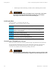
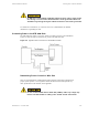
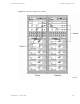
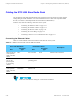
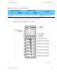
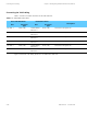
Table Of Contents

Cabling the STR 3000 Base Radio Rack Chapter 5: Installing the Digital Simulcast Remote Site (10Base-2)
Cabling the STR 3000 Base Radio Rack
The components of the STR 3000 Base Radio rack are shipped as one unit and do not require separate
cabling during the initial installation. For more information on how to cable each component within
the rack, see Volume 8, Field Replaceable Units and Entities (68P81004Y55).
From the rack, make the following connections to the system:
• "Connecting the Ethernet Cables" on page 5-12
• "Connecting the Transmit Cables" on page 5-13
• "Connecting the Receive Cables" on page 5-14
• "Connecting the V.24 Cabling" on page 5-16
• "Connecting Cables for a Co-Located Remote Site" on page 5-17
Connecting the Ethernet Cables
Table 5-4 lists the Ethernet connections from the STR 3000 rack to the system.
Table 5-4 Ethernet Connections from the STR 3000 Rack
From STR 3000 Rack
Destination Device
Port
Connector
Type
Port
Connector
Type
Description
Ethernet Out port
on the junction
panel in the f
irst
cabinet
BNC
Port1onHub
RJ45
Ethernet LAN connection
Ethernet Out
port on the
junction panel
in succeeding
cabinets
BNC
Ethernet out on
preceding panel
RJ45
Ethernet LAN connection
Ethernet Out port
on the junc
tion
panel in the last
cabinet
BNC with 50 ohm
terminati
on
Terminator on
Ethernet O
ut
BNC
LAN termination
Both ends of the Ethernet cabling for a rack must be terminated.
5-12 68P81003Y71-O November 2002