
User's Manual


68P80801E35-A 9/1/2001 7
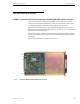
EBTS System Manual - Vol 2 Power Amplifier (PA)
PA Theory of Operation
PA Theory of Operation
Table 2 describes the basic functions of the PA circuitry. Figures 5 and 6 show the
functional block diagrams of 40W, 800 MHz and 70W, 800 MHz PA, respectively.
Figure 7 shows the functional block diagram of the 60W, 900 MHz PA. Figure 8
shows a functional block diagram of the 40W, 1500 MHz PA. Figure 9 shows a
functional block diagram of 800 MHz and 900 MHz QUAD PA.
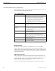
Table 2 Power Amplifier Circuitry
Circuit Description
DC/Metering Board • Serves as the main interface between the PA and the backplane board
• Accepts RF input from the Exciter via a blindmate RF connector
• Routes the RF input via a 50 Ω stripline to the Linear Driver Module
RF amplifier
• Routes the RF feedback from the RF Combiner/Peripheral Module
to the Exciter via a blindmate RF connector
• Provides digital alarm and metering information of the PA to the
BRC via the SPI bus
• Routes DC power to the fans and PA
• contains the thermistor that senses the PA temperature (800 MHz
QUAD and 900 MHz QUAD)
Linear Driver Module
(LDM)
• Contains two Class AB stages with the final stage in a parallel
configuration (70W-800 MHz, 40W-800 MHz, 800 MHz QUAD)
• Contains three cascaded Class AB stages with the first two stages
configured as distributed amplifiers and the final stage in parallel
configuration (900 MHz QUAD)
• Contains three cascaded Class AB stages with the final stage in
push-pull configuration (900 MHz)
• Contains four cascaded Class AB stages with the final stage in a
push-pull configuration (1500 MHz)
• Amplifies the low-level RF signal ~25 mW average power from the
Exciter via the DC/Metering Board (900 MHz)
• Amplifies the low level RF signal ~11mW average power from the
Exciter via the DC/Metering Board (70W-800 MHz, 800 MHz
QUAD*, 900 MHz QUAD*)
• Amplifies the low-level RF signal ~8 mW average power from the
Exciter via the DC/Metering Board (40W- 800 MHz, 1500MHz)
• Provides an output of:
~8 W (70W, 800MHz) average power
~4 W (40W, 800 MHz) average power
~6 W (800 MHz QUAD* and 900 MHz QUAD*) average power
~17 W (900MHz) average power
~16 W (1500MHz) average power
Interconnect Board
(70W-800 MHz, 40W-800
MHz, 800 QUAD, and 900
MHz QUAD
• Provides RF interconnection from the LDM to the RF Splitter board
• Provides DC supply filtering
NOTE: * The power outputs described in this section for the 800 QUAD and 900 QUAD PAs are references to the
single carrier mode operating at 52W average power out from the PA output connector.