
User's Manual


32 68P80801E35-A 9/1/2001
Troubleshooting EBTS System Manual - Vol 2
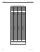
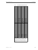
Generation 2/EBRC Single Channel Base Radio Backplane
Generation 2 Single Channel BR Backplane Connections
All external equipment connections are made on the Base Radio backplane.
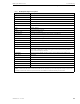
Table 4 lists and describes each of the connectors on the backplane.
Figure 4 shows the locations of the Generation 2 Base Radio external connections.
Table 4 Generation 2 Base Radio Backplane Connectors
Connector Module Description Type
P1 EBRC Signal 96 pin EURO
P2 Rx Signal 48 pin AMP Z-Pack
Futurebus
P3 Rx RF Harting Harpac
P4 not used not used not used
P5 EX Signal 96 pin EURO
P6 PA Signal 96 pin EURO
P7 External/Alarm Signal DB25
P8 External/RS232 Signal DB9
P9 PS Signal 78 pin AMP Teledensity
P10 Ethernet B/5 MHz Spare not used/not populated BNC blindmate
P11 Ethernet Signal BNC Blindmate
P12 DC Input -48 VDC IN (not part of the
backplane assembly)
8 pin AMP 530521-3
P13 5 MHz/ 1 PPS Signal BNC
P14 External/EX RF (EX to PA) SMA blindmate
P15 External/EX EX Feedback SMA blindmate
P16 External/PA PA Feedback SMA blindmate
P17 External/PA PA IN SMA blindmate
P18 External/PA PA OUT SMA blindmate
P19 Rx Branch 1 RF SMA
P20 Rx Branch 2 RF SMA
P21 Rx Branch 3 RF SMA