
User's Manual


C A N O P Y
Motorola Wireless Internet Platform
Page 16
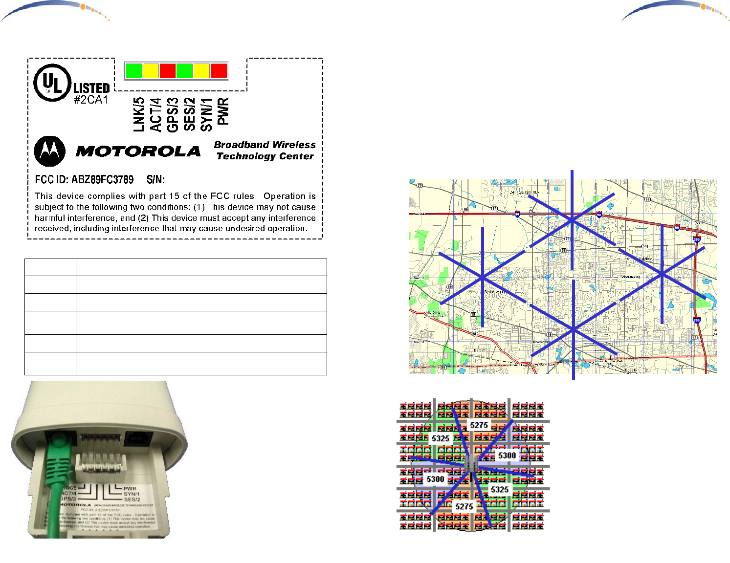
LED Display
In Normal Operating Mode the
LED indicators inside the Canopy
AP Unit provide various status
states. Each adjacent LED
employs a different colored LED
to help you distinguish one from
another. There are no color
coded meanings associated with
RED, YELLOW, or GREEN.
PWR
RED – Indicates the Canopy AP is powered
SYN/1
YELLOW – indicates AP Unit is operational
SES/2
GREEN – not used on the AP Unit
GPS/3
RED – indicates Sync input is active, if Sync Input is
configured as an input.
ACT/4
YELLOW – 10/100BaseT link activity, RX or TX
LNK/5
GREEN – 10/100BaseT link indicator
0A003E-XXXXXX
C A N O P Y
Motorola Wireless Internet Platform
Page 9
Planning Multiple Canopy AP Units
- Once the Canopy AP Units have been assigned unique IP addresses,
Sync Input, mounted, and connected to the Canopy AP Junctions, they
should be configured according to a frequency plan. Construct a
diagram of all the installed Canopy AP Units, and label each with the
assigned unique IP address and identify the Sync Master for each site
… preferably on a map overlay. This will become useful later when
providing directions for configuring Canopy Subscriber Modules.
Consider the example below depicting 24 Canopy AP Units at 4 sites.
192.168.1.3192.168.1.2
192.168.1.7
192.168.1.6
Master
192.168.1.5
192.168.1.4
192.168.1.13192.168.1.8
192.168.1.12
192.168.1.9
Master
192.168.1.10
192.168.1.11
192.168.1.17192.168.1.14
192.168.1.19
192.168.1.15
Master
192.168.1.16
192.168.1.18
192.168.1.25192.168.1.20
192.168.1.24
192.168.1.21
Master
192.168.1.22
192.168.1.23
- Using the configured IP addresses,
go to the configuration tab on the
internal web pages for each Canopy
AP Unit.
- Select an RF frequency for each
Canopy AP Unit based on it’s
direction / orientation using the
example guide shown at the left.
Units should be assigned different
frequencies in each adjacent cell,
while cells pointed in opposite
directions may use the same fre-
quency.